-

Getting Started 16
-

Maintenance 14
-

Troubleshooting 14
-

Repair 8
-

Laser 101 3
-

Materials 10
-

Accessories 20
-

Multi-Roller 7
-

LightBurn 9
Step Length Test - Multi-Roller


Overview
What you will learn
In this guide, you will learn how to adjust step length when using the Multi-Roller with your MIRA or NOVA.
When to do this
Step length should be tested when first setting up the Multi-Roller, or if a job ran with the Multi-Roller seems to engrave with different dimensions/proportions than were set when creating the job in LightBurn.
What you need
- Multi-Roller
- USB drive that came with the machine (attached to machine ignition key)
- Calipers
- Test Cup
- Laser Safety Glasses
What is Step Length?
Step length refers to the distance or angle the motor shaft moves with each step of operation.
Stepper motors, which is the motor the Multi-Roller uses, are unique in that they move in discrete steps rather than continuously rotating like other types of motors. These steps are precise and predictable, allowing for accurate control over the motor's position and movement.
If the value for step length is incorrect in the settings, it will cause designs run with the rotary to come out with incorrect dimensions, due to the motor either over or under turning the rollers and cups.
Testing Step Length
Prerequisites
Before running a step length test for the Multi-Roller, ensure the following points are true.
- The Multi-Roller is set up in the machine properly.
- There is a test piece set in the REAR RIGHT slot of the Multi-Roller.
- The origin is set to the proper position on the test piece and it is properly in focus.
- The rotary settings have been flashed to the machine.
If the above points are not true, see our AEON Laser Knowledge Base article on Multi-Roller setup to get to this point.
Test Procedure
IMPORTANT: Step length adjustments MUST be done in mm.
- speed of 50 mm/s and power ranging between 30-40%. Once completed, send the file to the machine.
- For larger designs or full wraps, opt for a 100 mm by 10 mm rectangle instead of a square. The process remains the same.
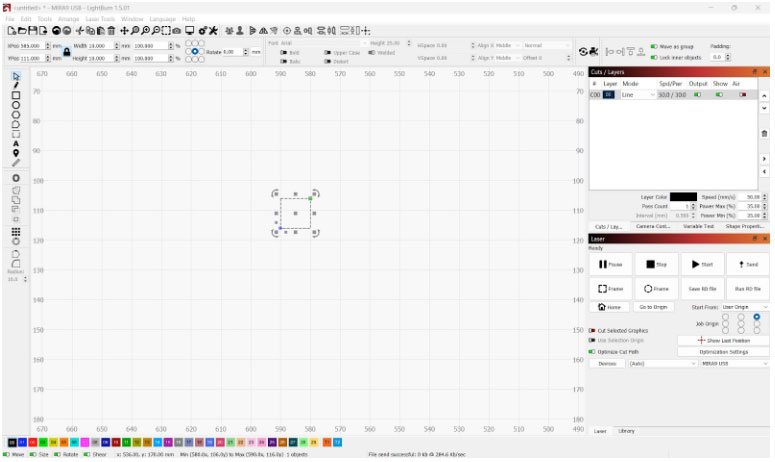
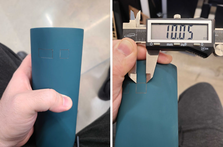
- Run the file on the cup.
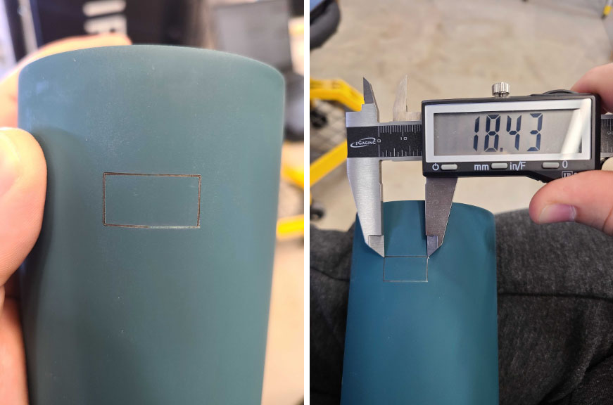
- Remove the cup from the rotary and measure the engraved line's distance along both the X and Y axes. The adjustment process is identical for both axes, so this guide will only cover a Y axis adjustment in detail.
- The Y axis refers to the lines engraved when the laser head was stationary while the rollers moved the cup. Typically, these are the top and bottom lines when holding the cup upright.
- The X axis refers to the lines engraved when the laser head was moving while the rollers were stationary. Typically, these are the left and right lines when holding the cup upright.
NOTE: It is CRITICAL to make all measurements from this point forward as precise as possible. When measuring, measure from the center of the engraved line to the center of the other engraved line at the corners of the box.
If doing a 100 mm rectangle, measure with a cloth tape measure. Calipers will not measure the curve accurately. - The Y axis refers to the lines engraved when the laser head was stationary while the rollers moved the cup. Typically, these are the top and bottom lines when holding the cup upright.
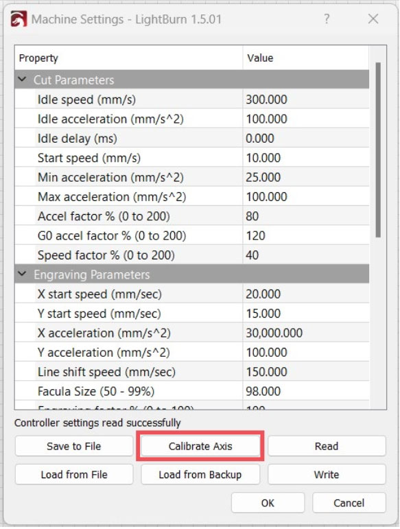
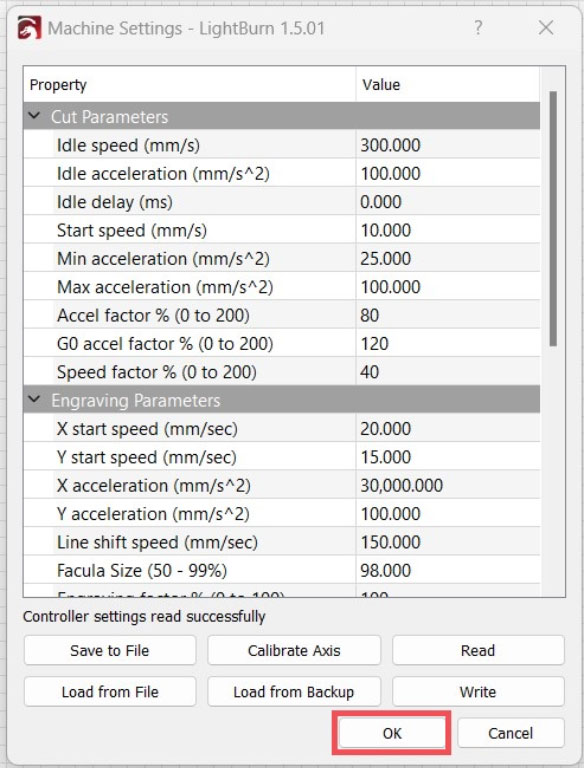
- In LightBurn, open the “Machine Settings” window. Once open, click on the “Calibrate Axis” button towards the bottom of the window.
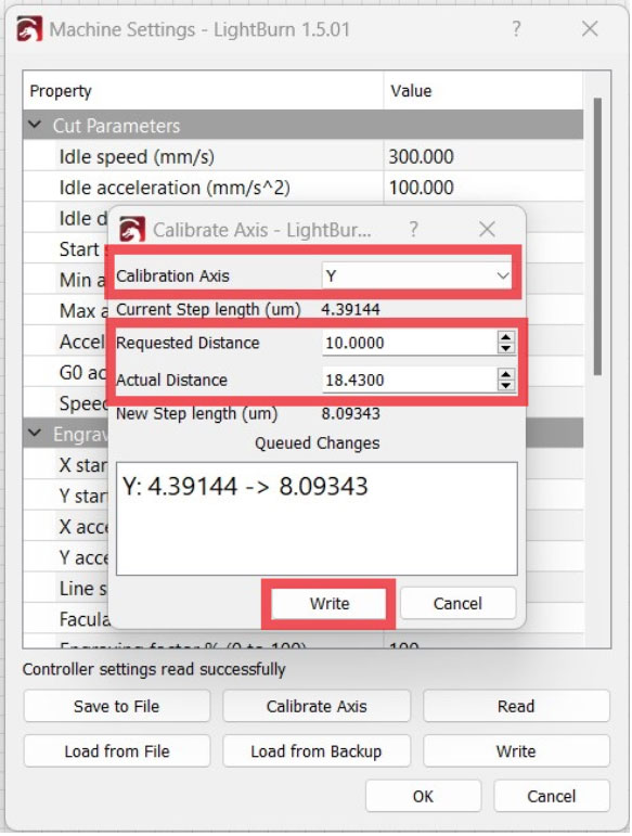
- Input the following information into the “Calibrate Axis” window:
- Select the axis that was measured and needs adjustment from the “Calibration Axis” dropdown. For this guide, we selected the Y axis.
- Input the original files size, in mm, into the “Requested Distance” input box.
- Input the measured distance from the actual engraving on the cup into the “Actual Distance” input box.
- Once all information has been input, click “Write” at the bottom of the “Calibrate Axis” window. LightBurn will automatically calculate the needed step length and change it for you.
NOTE: If the X axis needs adjustment, perform Steps 3-5 again. Select X as the calibration axis instead of Y.
- Click “OK” at the bottom of the “Machine settings” window to close it.
- Re-position the cup and re-run the square test. No need to resend the file, as this adjustment only affects how the motor moves, not the file's set dimensions.
- Measure the new square.
- The square should now be within tolerance (+/- 0.5 mm), assuming precise initial measurements. If not, repeat the process.
- Return to LightBurn. Save the adjusted settings and overwrite them on the flash drive for future use.
- To save, click on “Save to File” at the bottom of the “Machine Settings” window.
If you have any questions or concerns, please send us an email at support@aeonlaser.us for the fastest service. If your laser is malfunctioning, please submit a support ticket.
Did you find this document helpful? Let us know what you liked or what we can improve on by sending an email to helpusgrow@aeonlaser.us.
Happy Lasering!


