Chiller Flow Sensor Replacement
Overview
What you will learn
In this guide, you will learn how to replace your Chiller Flow Sensor.
When to do this
The Chiller Flow Sensor should be replaced as necessary should a failure occur.
What you need
- Phillips Head Screwdriver
- Wire Strippers
- Wire Cutters (or an equivalent cutting utensil)
- Heat Gun
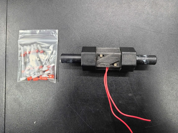
- Replacement Flow Sensor
- Solder Seals
- Zip Ties
- Paper Towels
- Water Container
Steps
WARNING: This process requires a heat gun to be used to activate the solder seals. This is a burn risk, be cautious while using the heat gun during the process.
- Before you begin, make sure the machine is OFF and unplugged.
- Follow our chiller removal guide to safely drain and remove the chiller.
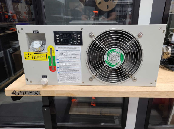
Chiller - Use a Phillips head screwdriver to remove the rear cover plate mounting bolts (top and rear perimeter) from the chiller.
CAUTION: Do not touch any screws on the face of the chiller after it has been removed.
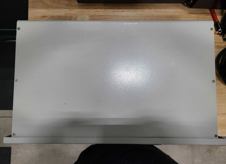
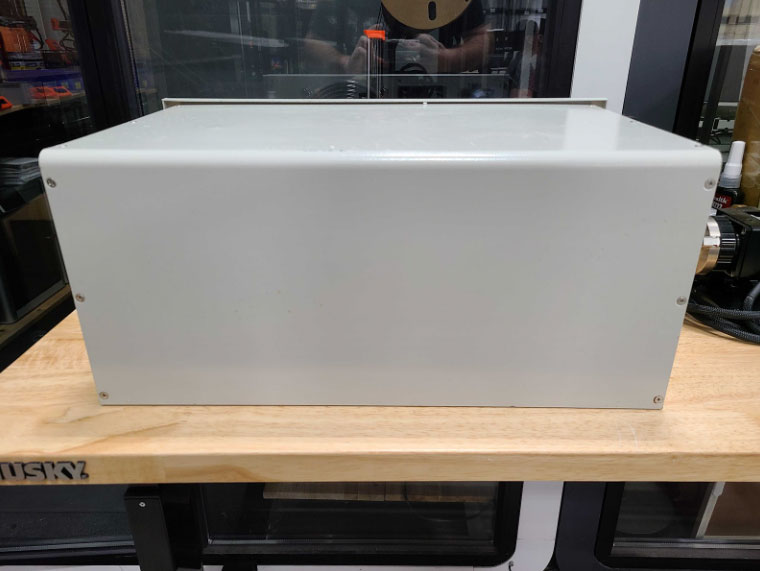
- Take off the cover plate and set aside.
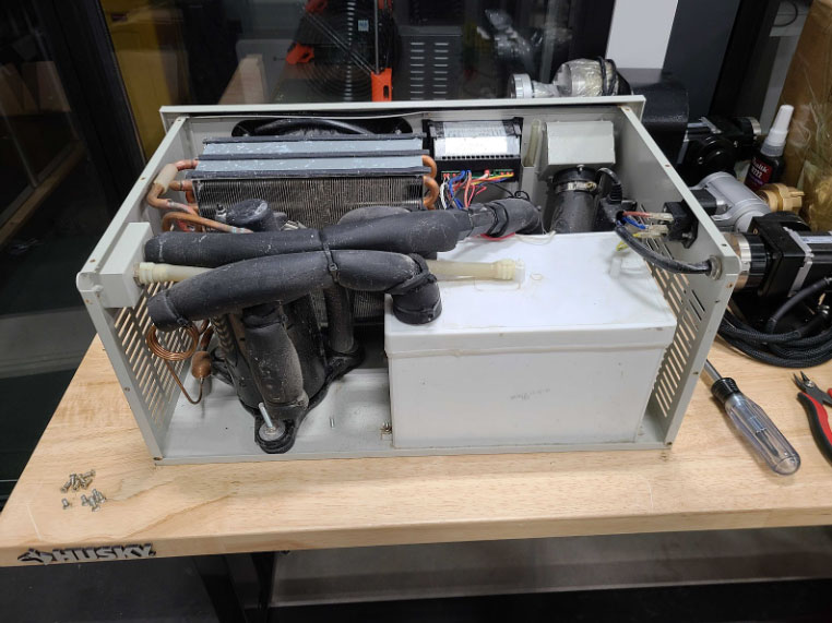
Chiller without cover plate - Locate the flow sensor, noting the arrow's direction. Take a photo for reference.
The replacement sensor MUST be installed in the same direction.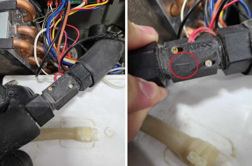
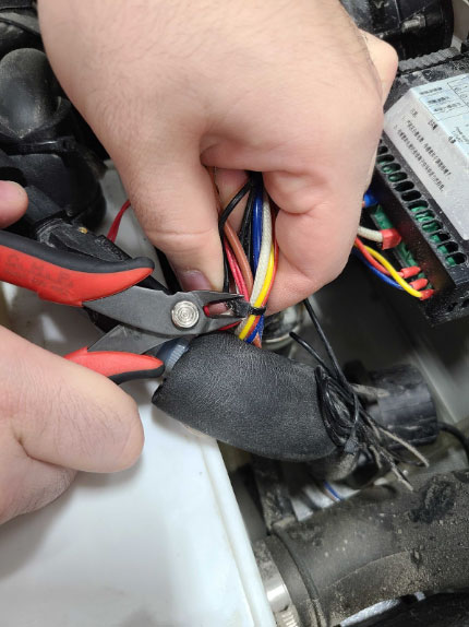
Flow sensor - Cut zip ties binding the flow sensor wires. Be careful not to damage any wiring.
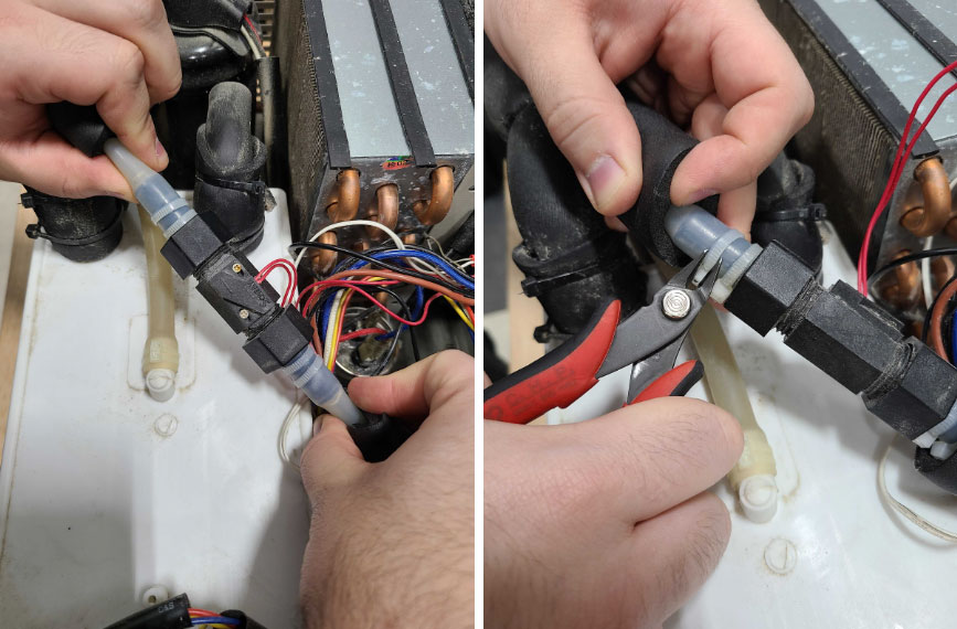
Cut zip ties - Slide the foam cover back and cut ties connecting silicon tubing to the flow sensor.
CAUTION: Take care to not accidentally damage the silicon tubing connecting to the sensor. If any damage does occur, please submit a support ticket or send us an email at support@aeonlaser.us
- Cut the two red wires from the old sensor, ensuring enough slack for soldering. Cutting closer to the bad sensor is advised.
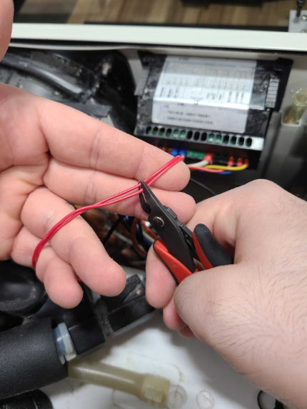
Red wires - Pull tubes off the old sensor and set it aside.
NOTE: There is likely still some water in the sensor and tubing. Have some paper towels ready to catch any spills.
- Install the silicon tubes to the new sensor, ensuring the arrow faces the same direction. Secure the tubes to the new sensor with some zip ties.
- Strip about ½” of sheathing from both the ends of the wires on the new sensor, as well as the wire ends that are still in the chiller from where the old sensor was attached.
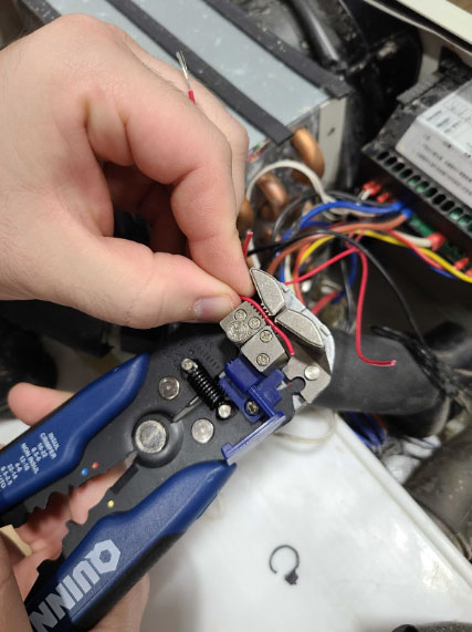
Strip sheathing - Twist the ends of all stripped wires into a tight coil.
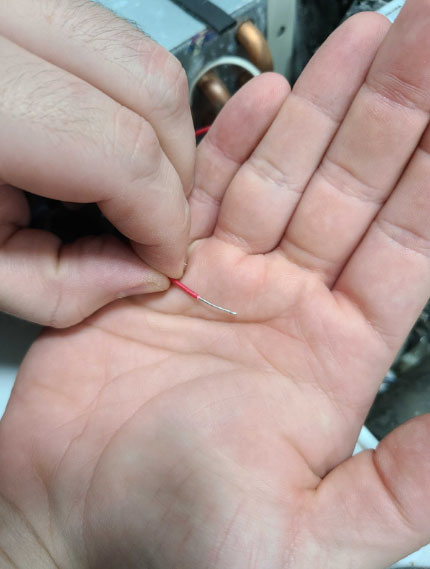
- Slip a solder seal onto each wire coming from the new sensor (2 seals total).
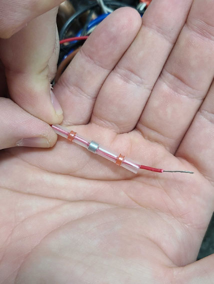
- Loop the ends of the twisted wires into a small hook shape.
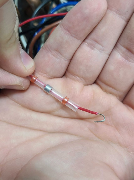
- Take one wire with a solder seal (wire from the new sensor), and hook it to one of the wires without the solder seal (wiring from the old sensor that is in the chiller). Pinch the hooks together to secure the connection.
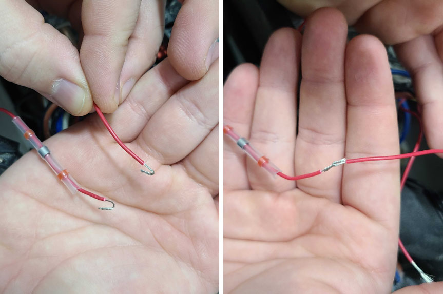
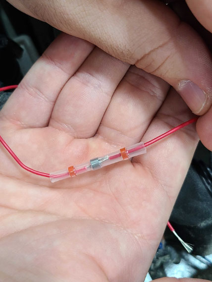
- Slip the solder seal over the wire. The gray/silver bead in the center of the seal MUST be positioned directly over the wire connection. The red spots on either end of the seal should be over the sheathing of the wires on each side.
- Repeat Steps 15 and 16 with the remaining two wires.
- Use a heat gun to activate both solder seals, one at a time. The heat should be applied in a steady, broad sweeping motion from end to end of the seal until fully activated. Ensure all sides of the seal are heated as well, gently rotate as needed.
- You will know the seal has activated properly when you see the center gray bead melts into a metallic silver color. The plastic of the seal will also shrink to fit the wire. The red spots on either end will melt and release as well, this is a glue to secure the seal.
WARNING: Avoid any skin contact on the end of the heat gun and exposed metal in the area the heat gun was pointed, as it is a potential burn risk. Seek medical attention if you get burned.
CAUTION: Try to angle the heat gun so the heat is moving outside of the chiller. Avoid pointing the heat gun towards other components in the chiller to avoid damage.
CAUTION: Do not overheat the area. If there is smoking or burning coming from the area, remove the heat and allow it to cool.
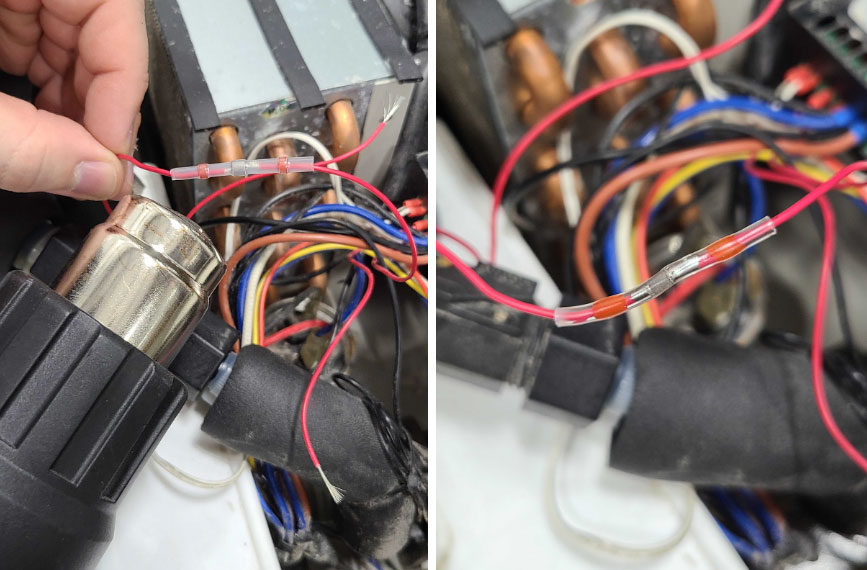
- Allow both solder seals to fully cool. They should turn a smoky white color when cool. Do not pull on the wires while the solder is still hot. The connection can come undone and will need to be restripped and soldered.
WARNING: Avoid any skin contact on the solder seals after heating, as it is a potential burn risk. Seek medical attention if you get burned.

Seal that is still hot (top) and one that has cooled properly (bottom) - Once fully cooled, give each solder connection a light tug to ensure it is secure.
That's it!
If you have any questions or concerns, please send us an email at support@aeonlaser.us for the fastest service. If your laser is malfunctioning, please submit a support ticket.
Did you find this document helpful? Let us know what you liked or what we can improve on by sending an email to helpusgrow@aeonlaser.us.
Happy Lasering!


