-

Getting Started 16
-

Maintenance 14
-

Troubleshooting 14
-

Repair 8
-

Laser 101 3
-

Materials 10
-

Accessories 20
-

Multi-Roller 7
-

LightBurn 9
Install a 4" Lens NOVA


Overview
What you will learn
In this guide, you will learn how to safely install the 4” lens on your NOVA and ensure it functions properly.
When to do this
The 4” lens should be installed when you are wanting to cut thicker materials. It can also help provide more clearance between the laser head and material when engraving into items with high sides, like serving bowls or trays.
What you need
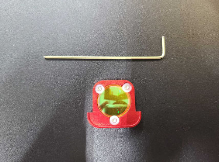
- Allen Keys
- Microfiber Cloth
- 4” (101.6 mm) Lens
- NOVA Lens Tool
- Powder Free Nitrile Gloves
- Flat Piece of Scrap Material
- Pen or Marker
Need assistance?
Book time with a qualified technician and get help with Swapping Lenses.
CAUTION: Avoid touching any optics directly with your skin. Doing so can cause irreparable damage to the coating and will require the optic to be replaced. It is recommended to wear the proper type of gloves when touching optics.
Video
Remove the 2.5” Lens
- Place a microfiber cloth under the laser head on the honeycomb or blades to catch any small pieces that would otherwise drop into the bed of the machine.
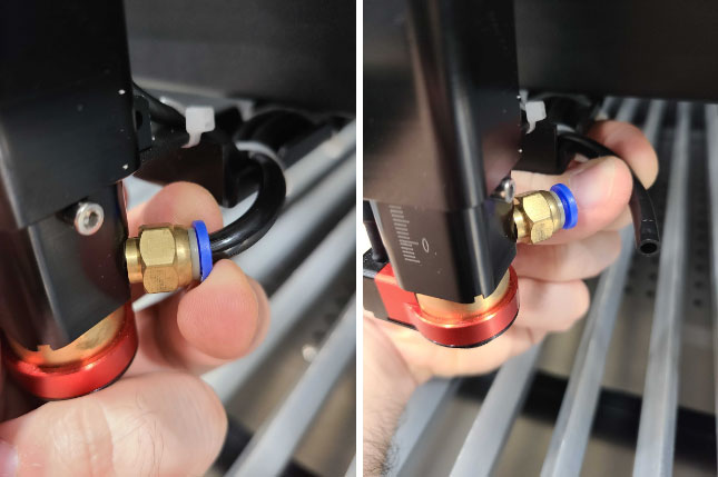
- Remove the air hose from the air fitting on the laser head by pushing on the blue retainer ring and pulling the air hose free.
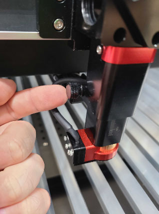
- On the left side of the laser head, loosen the thumb screw until the lens housing is released.
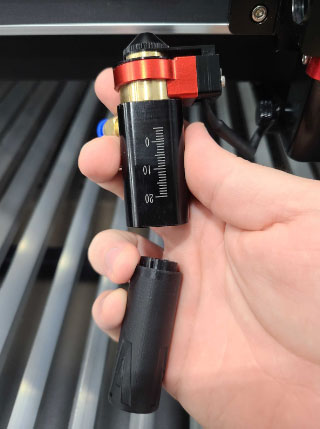
- Remove the lens housing from the laser head and flip it upside down.
- Using the NOVA lens tool from the tool kit, gently unscrew the retainer ring inside the lens housing until the retainer ring, silicone O-ring, and lens is fully removed.
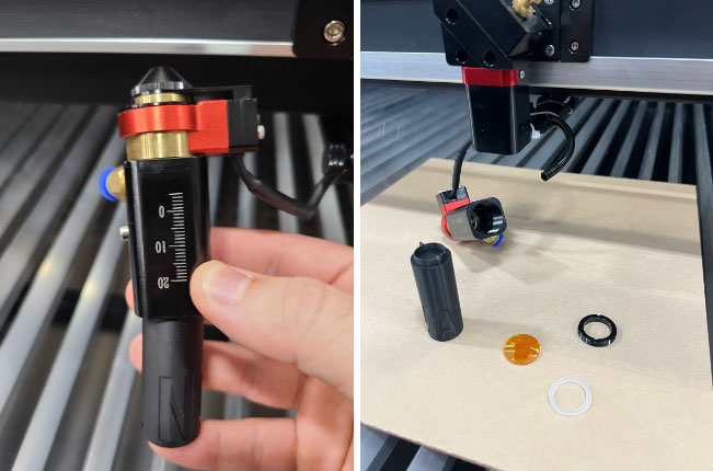
- Reinstall the EMPTY sliding lens housing back into the laser head. Set the slider approximately to marker 10 on the housing.
- Tighten the thumb screw until the lens housing is firmly in place.
- Push the air hose back into the air fitting on the lens housing and lightly tug to ensure it is seated fully.
Install the 4” Lens
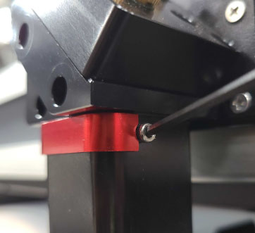
- Locate the 4” lens housing at the top of the laser head. It looks like a small red rectangle.
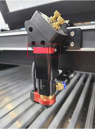
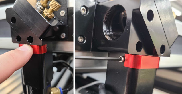
- Use an Allen key (1.5 mm or 2 mm, depending on generation of machine) to remove the mounting bolts on either side of the 4” lens housing. Set the bolts aside for reinstallation later.
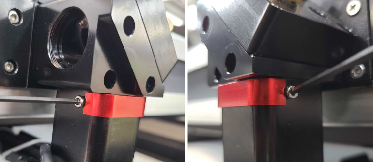
- Carefully remove the 4” lens housing from its slot in the laser head.
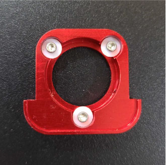
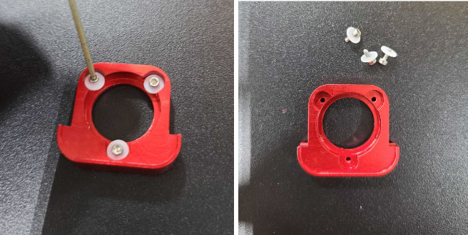
- Use a 1.5 mm Allen key to remove the tiny lens mounting bolts and plastic white washers from the housing, and set them aside.
- Retrieve and carefully place the 4” (101.6 mm) lens into the 4” lens housing. Ensure the lens is installed in the proper direction, dome side up. When looking at the lens from the top of the housing you should see your reflection right side up, as if you were looking into a tiny mirror.
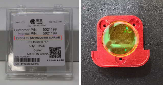
NOTE: There may be an arrow on the ridge of the lens indicating the correct orientation as well.
- Reinstall the tiny lens mounting bolts with a 1.5 mm Allen key. Ensure the white washers are in place. It is good practice to get all three bolts threaded before fully seating. Doing so helps keep the lens from becoming incorrectly seated in the housing.
CAUTION: DO NOT overtighten the lens mounting bolts. Doing so can cause damage to the lens.
- Return the 4” lens housing into its original position in the laser head.
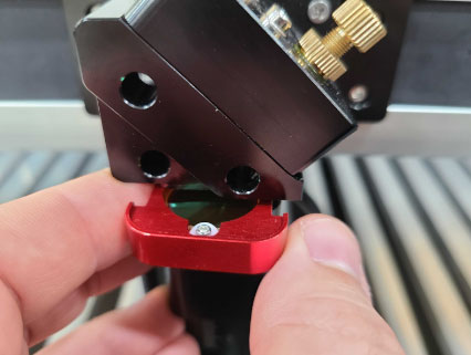
- Push firmly on the housing to ensure it is seated fully in the laser head. Then, reinstall the mounting bolts removed in Step 2 to either side of the laser head to secure the housing.
That's it! The 4” lens is now installed and ready to use. It is recommended you run through a 5 point test to ensure the alignment through the newly installed lens is looking good and allowing the beam to fully exit the nozzle. See our AEON Laser Knowledge Base article on the 5 Point Test for NOVA for reference.
Calibrating the Auto Focus
The 4” lens is capable of utilizing the auto-focus function on the NOVA; however, it requires determining the accurate setting for the sliding lens housing. In the preceding steps, you were advised to set the slider approximately to marker 10 on the housing, which serves as an initial depth setting. While this should be in proximity to the correct depth, further adjustments are necessary to achieve the optimal setting. Conducting a brief focal ramp test is recommended for precise calibration of the sliding lens housing's position. This ensures that when auto-focusing with the machine, the 4” lens is accurately focused.
The need to calibrate the positioning of the sliding lens housing for the 4” lens, as opposed to the 2.5” lens, arises from the fact that the 2.5” lens maintains a fixed distance from the auto focus sensor. This constant distance is maintained because the 2.5” lens is securely installed within the sliding housing, which the auto focus sensor is also attached to. On the other hand, the 4” lens is physically mounted in the laser head chassis, resulting in variable distance from the bed or material. The distance of the 4” lens from the material depends on the depth setting of the sliding lens housing.
The recommended process for finding the proper setting for the sliding housing is as follows:
NOTE: This process is written with the NOVA Elite in mind. If you have a SuperNOVA, ensure the testing is done with the CO2 tube.
- Place a flat piece of scrap material into the bed.
- Auto focus onto the material.
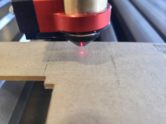
- Close the machine's lid and quickly tap the pulse button on the keypad.
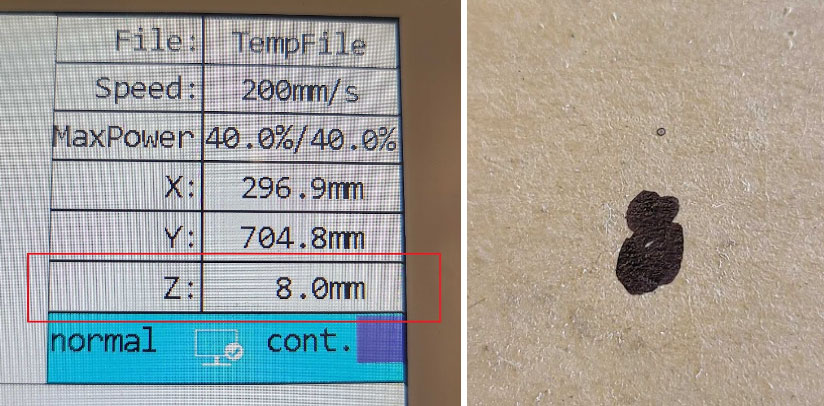
- Remove the scrap material from the bed, and inspect the pulse mark. DO NOT move the laser head or the bed.
- Look at the “Z” value on the keypad. Write the value under the pulse mark, and reposition the material under the laser head. Ensure the laser head will pulse on a fresh piece of the material. It is best practice to keep all of the pulse marks done while testing in a linear fashion to avoid confusion.
- Once the material is repositioned, use the “Z DOWN” arrow to lower the bed down 1 mm.
- Close the machine's lid and quickly tap the pulse button on the keypad.
- Remove the scrap material from the bed, and inspect the pulse mark. DO NOT move the laser head or the bed.
- Look at the “Z” value on the keypad. Write the value under the pulse mark, and reposition the material under the laser head. Ensure the laser head will pulse on a fresh piece of the material.
- Repeat Steps 6-9 once more, for a total of 3 pulse marks.
- Once the material is repositioned, auto focus onto the material.
- Use the “Z UP” arrow to raise the bed up 1 mm.
- Close the machine's lid and quickly tap the pulse button on the keypad.
- Remove the scrap material from the bed, and inspect the pulse mark. DO NOT move the laser head or the bed.
- Look at the “Z” value on the keypad. Write the value under the pulse mark, and reposition the material under the laser head. Ensure the laser head will pulse on a fresh piece of the material.
- Repeat Steps 12-15 once more, for a grand total of 5 pulse marks.
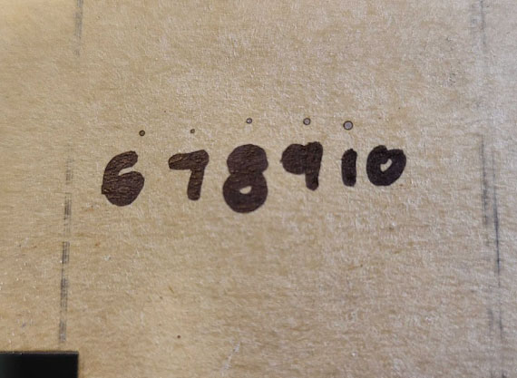
- Closely inspect the pulse marks. If the current setting is close, the range of dots should look like a gradient, with the dot size likely increasing on the outer ends of the spectrum. If so:
- Identify which Z value looks to have the finest pulse mark. In the example picture above, it is clear upon close inspection that the pulse mark at a Z depth of 7 is smaller than the 6 and 8 depth marks.
- Find the difference between the fine pulse marks Z value and the Z value when auto focused.
- Adjust the slider in the appropriate direction based on the value found. For example, If the auto focus Z value is 8, and the best looking Z value was 7, the result would be to slide the housing from 10 to 9.
NOTE: Finding the most precise point is crucial in this calibration process. Look for a distinct dot that is finer than the others, with larger dots on either side, based on the test results. If the dots only appear to decrease in one direction, continue following the general process mentioned earlier. Adjust the bed using the Z arrows more in that specific direction after auto-focusing. Once you observe the gradient result, proceed to Step 17.
For increased precision, the focal ramp test can be repeated using .5 mm increments instead of 1 mm increments.
That's it! The auto focus for the 4” lens has been successfully calibrated. Take note of the marker value that proves effective for your setup, as this can serve as a consistent setting for the sliding housing once the optimal configuration is determined. If you wish to refine the focal distance and sliding lens housing with even greater precision, consider conducting the focal ramp test again, this time adjusting in .5 mm increments.
You should be all set and ready to run jobs with the 4” lens now. Happy Lasering!
If you have any questions or concerns, please send us an email at support@aeonlaser.us for the fastest service. If your laser is malfunctioning, please submit a support ticket.
Did you find this document helpful? Let us know what you liked or what we can improve on by sending an email to helpusgrow@aeonlaser.us.
Happy Lasering!


