-

Getting Started 16
-

Maintenance 14
-

Troubleshooting 14
-
Repair 8
-

Laser 101 3
-

Materials 10
-

Accessories 20
-

Multi-Roller 7
-

LightBurn 9
LightBurn Camera Setup


Calibrating the Lightburn Camera - MIRA & NOVA
Overview
What you will learn
In this article you will learn how to set up the Lightburn Camera for your machine, the basic use options available, and common issues.
Why do this
Get a bird's eye view of your workspace right on your computer screen for quick and accurate placement of your design. The camera will help you line up designs on flat materials and can be used to trace objects placed in the bed of the machine into lightburn as a vector.
What you need
- Computer with Lightburn
- Machine with Lightburn Camera
- ⅛”-¼” Sheet of Material (must be opaque and at least 12”x12”)
- USB Cable
Need assistance?
Book time with a qualified technician and get help setting up a LightBurn Camera.
Video
Steps
- Power the machine ON and allow it to fully reset.
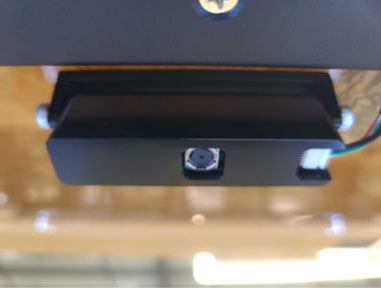
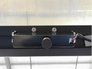
NOTE: If you have a NOVA, remove the lens cap from the camera.
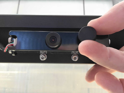
Lightburn Camera Lens Cap - Plug the USB cord into the USB port on the machine as well as into your computer.
- In Lightburn:
Ensure that the USB profile for the machine is selected in the “Laser” window.
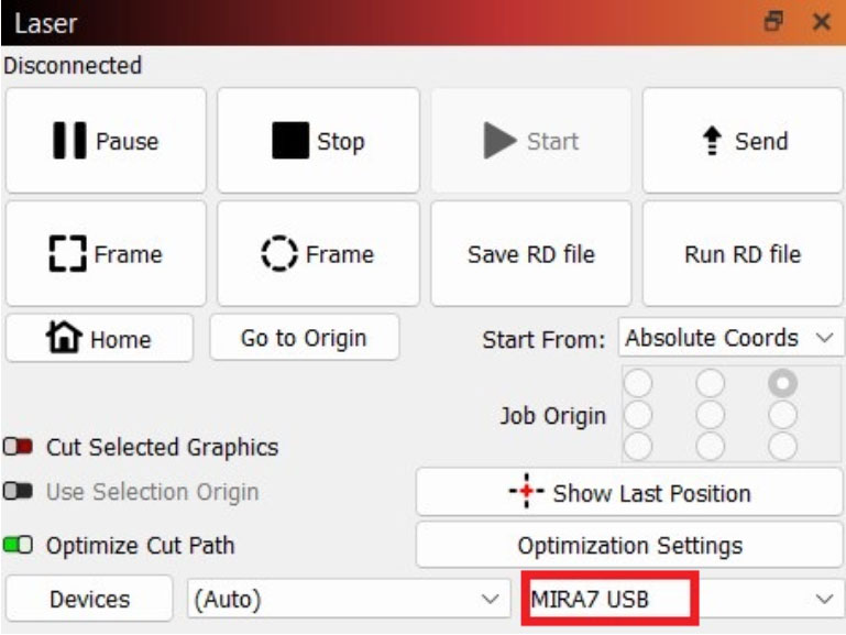
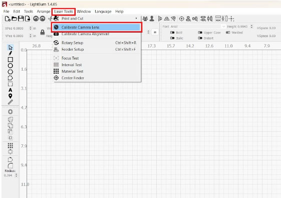
Chose USB profile for your machine Click on the “Laser Tools” dropdown window.
Select “Calibrate Camera Lens”.
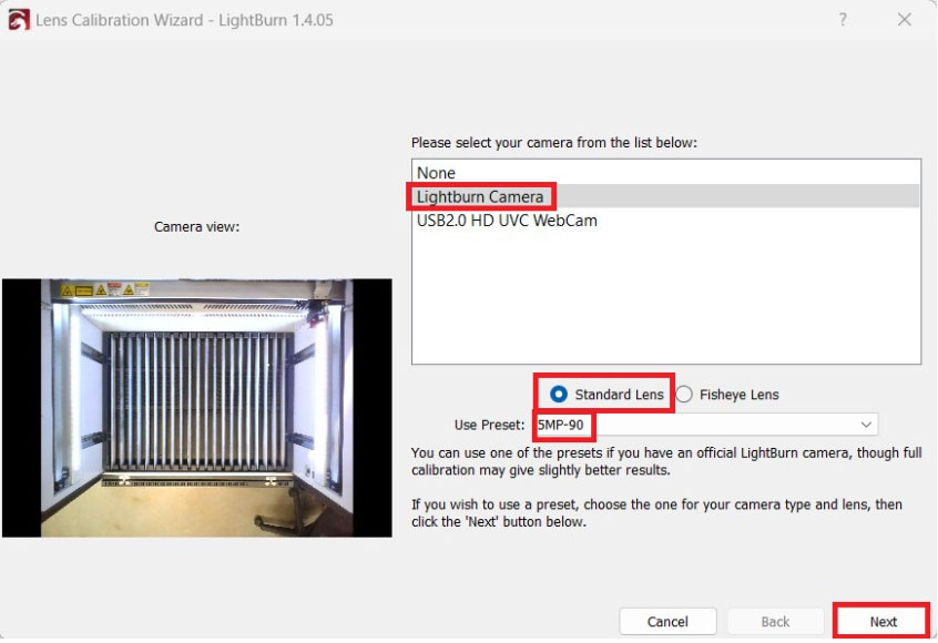
Select Calibrate Camera Lens - In the “Lens Calibration Wizard” window select the “Lightburn Camera” or “Aeon Camera” from the list (depending on generation of machine).
- Click the “Standard Lens” selection bubble below the camera selection list.
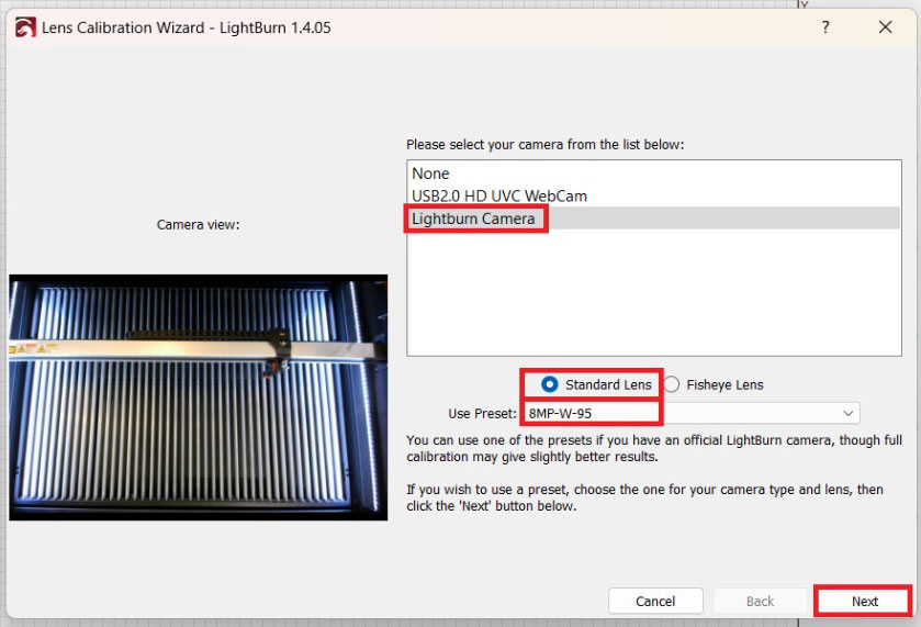
- From the “User Preset” dropdown, select the option for your machine.
Use preset 5MP-90 for MIRAs.
5MP-90 for MIRAs Use preset 8MP-W-95 for NOVAs.
8MP-W-95 for NOVAs CAUTION: If you do not see the options above and are instead on a screen with a grid of dots, please submit a support ticket or send us an email at support@aeonlaser.us.
- Click “Next”.
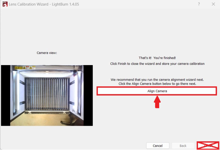
- In the “Camera Alignment Wizard” window, click “Align Camera”.
NOTE: DO NOT click “Finish” yet, there is still more to do.
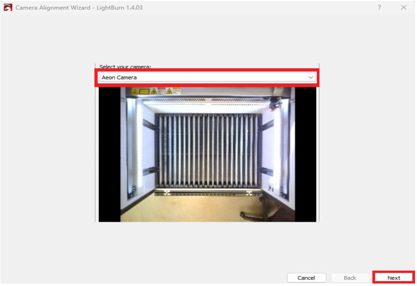
Click “Align Camera”. DO NOT click "Finish" - Select “Lightburn Camera” (or “Aeon Camera”) from the dropdown list, then click “Next”.
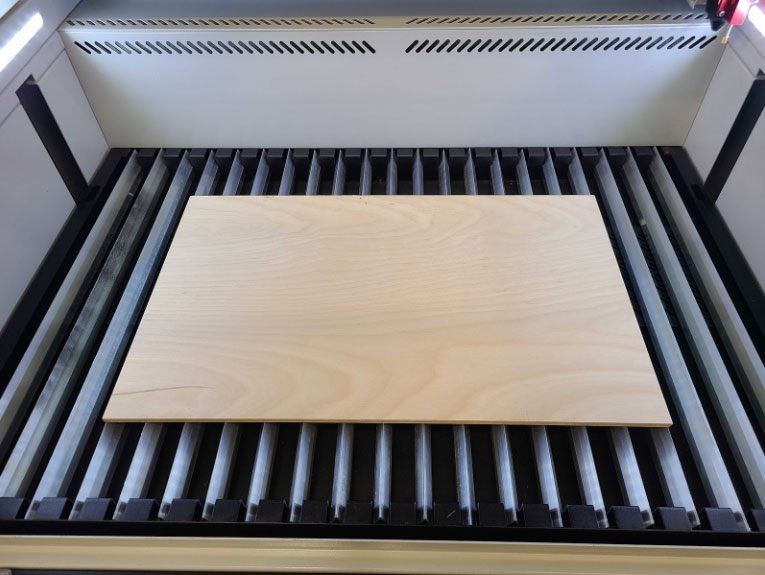
Select "Lightburn Camera" or "Aeon Camera" - Move to the machine and place the sheet of material into the center of the laser bed.
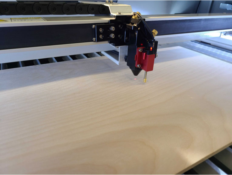
Sheet of material on center of laser bed - Auto focus (or manually focus) onto the board.
For auto focusing with a MIRA:
- Position the laser head over the center of the board.
- Press “Z/U” on the keypad.
- Use the “UP” and “DOWN” arrow keys to navigate to the “Auto Focus” option in the menu.
- Press “Enter” and allow the machine to auto focus.
For auto focusing with a NOVA:
- Position the laser head over the center of the material.
- Press “Focus” on the keypad and allow the machine to auto focus.
For manual focusing, see our Manual Focusing article.
- Back to Lightburn now; in the “Camera Alignment Wizard” window enter the following:
- Material Thickness: 0.000
- Fill Speed: 100
- Fill Power: 30
- Line speed : 60
- Line power : 25
- Scale: 100 for MIRAs; 150 for NOVAs
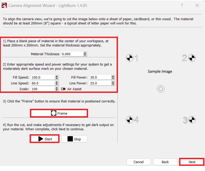
Camera Alignment Wizard - In the “Camera Alignment Wizard” window, click “Frame”.
Watch the red dot beneath the laser head as it frames the square. Adjust the material sheet as needed so that the frame stays within the borders of the material sheet. - Close the lid.
- In the “Camera Alignment Wizard” window click “Start”.
Allow the job to run to completion. Do not power the machine off or stop the job during this time, if possible. In case of an emergency, like a fire, press IN the Emergency Stop button to power the machine down and reach out to support. - Once the laser has finished running the job, click “Next” in the “Camera Alignment Wizard” window.
- Lift the lid of the machine. Once the lid is open, gently press up on the lid so it is fully opened, and allow it to settle back into its resting open position.
CAUTION: The lid MUST be pushed open fully and allowed to rest to ensure the camera is in the same position each time it is used. If this is not done, there is likely to be a deviation from where the file is placed in Lightburn to where the machine runs the job.
- Move the gantry so it is not obstructing the view of the board if needed.
- In the “Camera Alignment Wizard” window:
Click “Capture Image”.
Click “Next”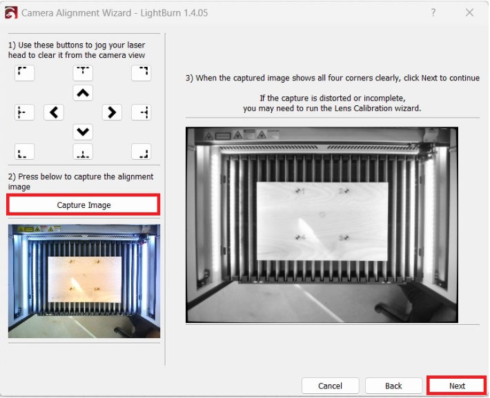
Camera Alignment Wizard: Capture Image - In the “Camera Alignment Wizard” window:
Zoom in on marker 1
Double click on the center of the marker 1 target.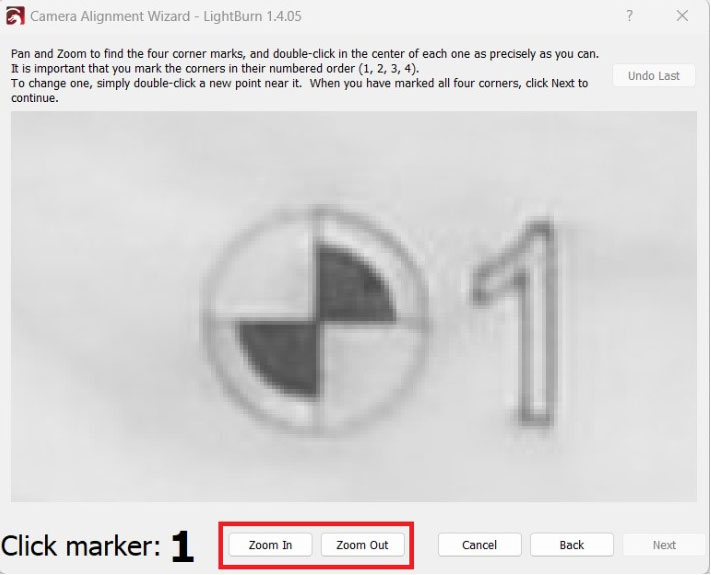
Marker 1 target 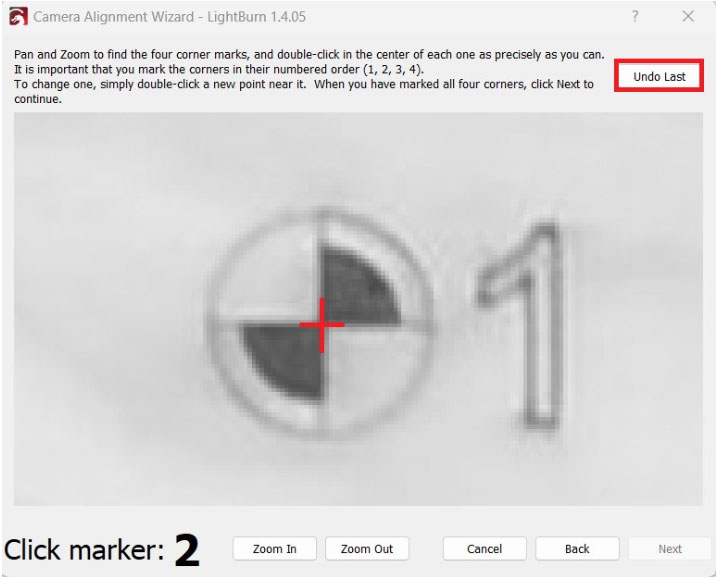
Marker 1 target NOTE: If you do not click on the exact center of the marker target, click “Undo Last” in the upper right corner of the “Camera Alignment Wizard” window and you can now double click on the center of the marker again.
CAUTION: You MUST be as precise to the center as possible, any deviations here will lead to deviations when using the camera for production.
- Zoom out from marker 1, and repeat Step 20 with the next three markers, in sequential order.
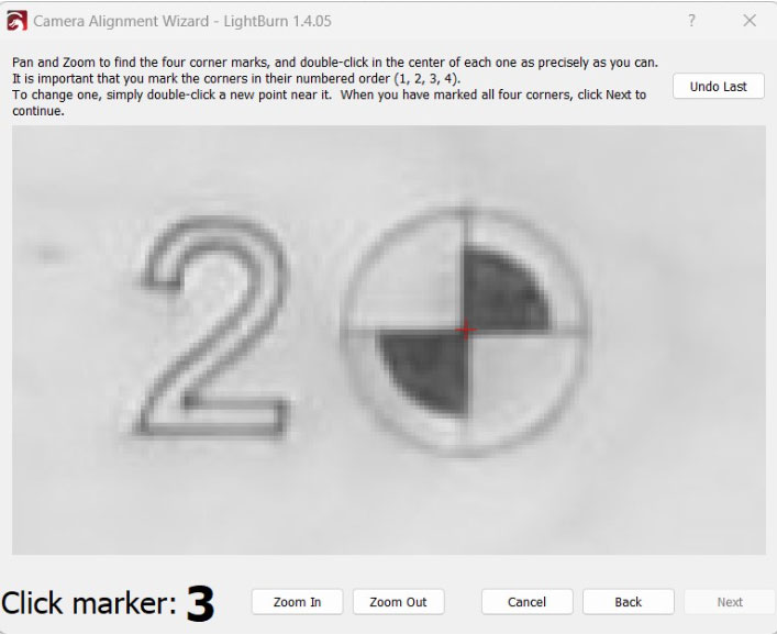
Marker 2 target 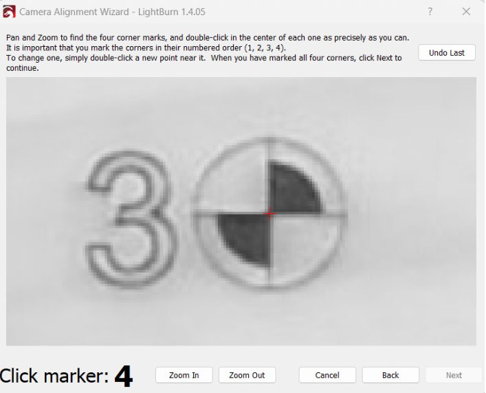
Marker 3 target 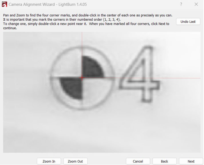
Marker 4 target - Once you have clicked on the centers of all four markers, click “Next”.
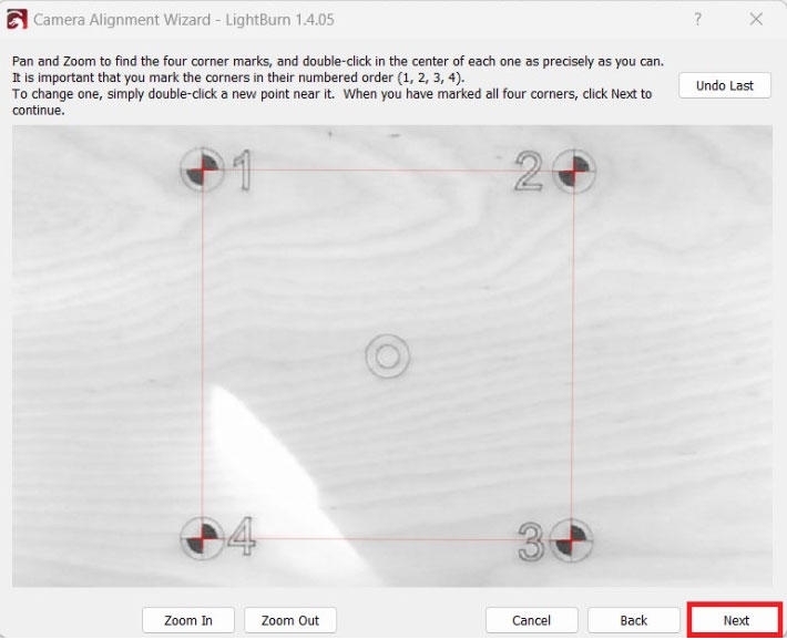
All four markers NOTE: If you have clicked all markers properly, there will be a red square present when zoomed out in the “Camera Alignment Wizard”.
- In the “Camera Alignment Wizard” window, click “Finish”.
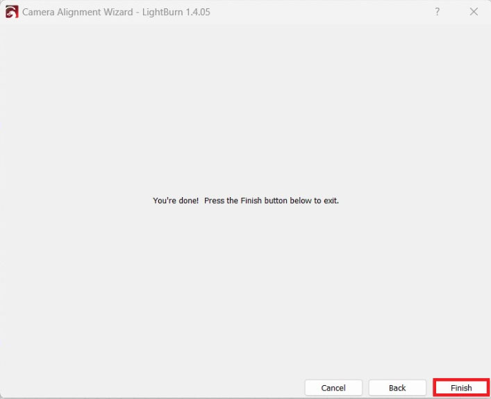
Camera Alignment Wizard
That's it, the camera is now calibrated and ready to use!
How to Use the Camera - The Basics
The camera will be controlled via the “Camera Control” tab/window in Lightburn. The lid should be open to properly use the camera. The calibration is also saved to the device profile that the calibration was performed with. If you have multiple device profiles, the calibration will need to be run on each of them.
Steps
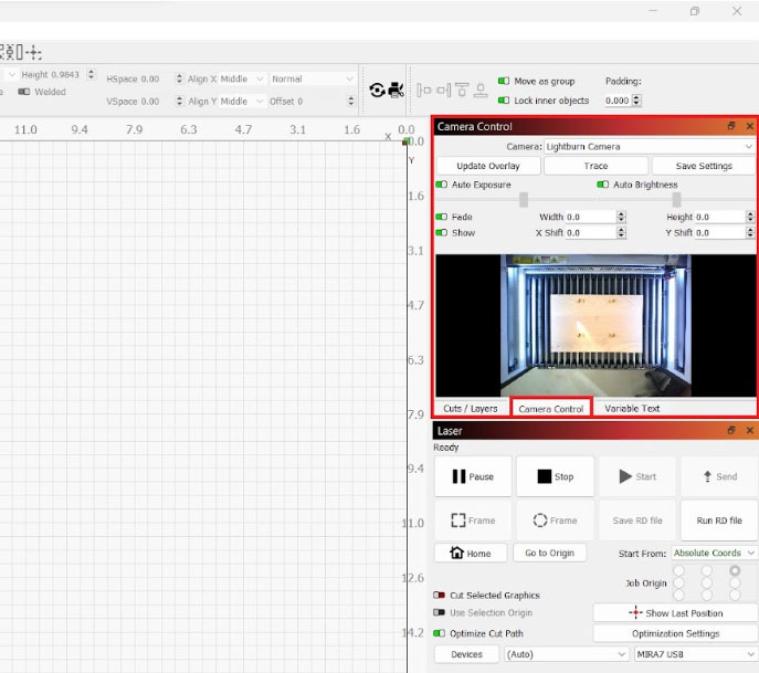
- Click on the “Camera Control” tab.
NOTE: If you do not see the “Camera Control” tab, click on “Window” along the top menu bar of Lightburn and ensure the “Camera Control” is checked in the dropdown.
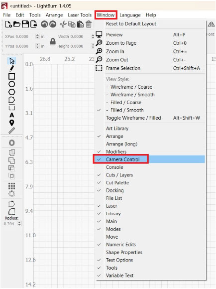
Window > Camera Control - Select “Lightburn Camera” or “Aeon Camera” from the dropdown list. This is the saved calibration setting that was done in the previous steps.
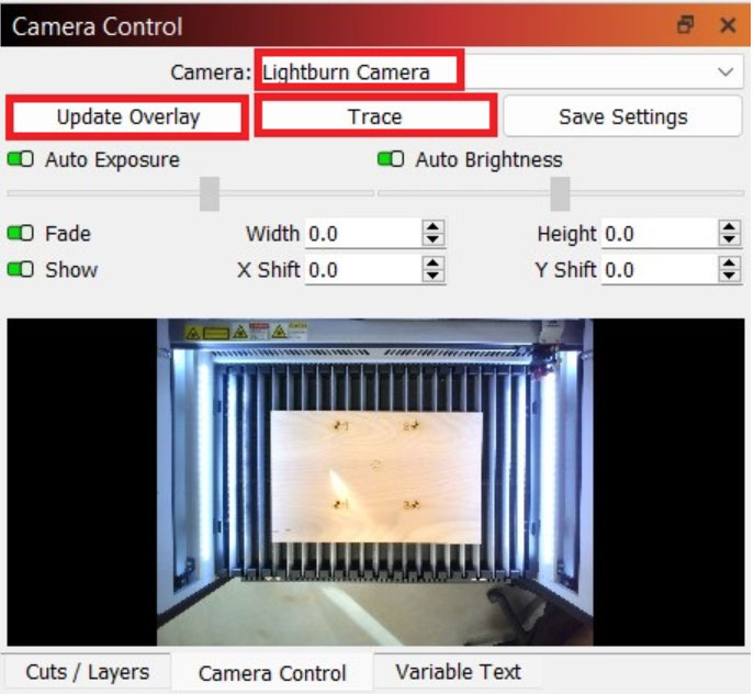
Select Lightburn Camera or Aeon Camera from dropdown - There are two main options to select from this window:
- Update Overlay:Clicking this option will cause the camera to take a picture and update the Lightburn display to show the image. This can be used to help place a file onto whatever flat material is in the bed. The camera uses the “Absolute Coords” start from/origin option to achieve this. For example, a good use case is when trying to fit a small file into the nooks and crannies on a piece of scrap material.
- Trace: Clicking this option will cause the camera to trace the outline of a piece that was put into the bed. For example, if you had a wrench set and wanted to make an inlay for a toolbox that each wrench would fit into. The wrenches could be positioned into the bed in the desired order and have their outlines traced. The machine and Lightburn would generate an outline of the objects so they can be cut in the same position they were laid out, or allow for the shapes to be adjusted as needed.
The camera will always use the “Absolute Coords” start from/origin option in Lightburn. Where the file is placed in the Lightburn window is where it will run on the bed. The camera will also generally have a deviation of up to +/- 1/8” deviation (3-4 millimeters), with the deviation more apparent towards the edges of the frame. The camera is only able to be used via a USB connection as well.
See this LightBurn Camera Demo video on what the camera can offer.
Common Issues and Failures
If you notice the file coming out too far from where it was placed in Lightburn, try the following:
- Ensure that the lid was pushed open fully and allowed to rest at its natural position. Update the overlay after moving the lid and try the file again.
- Run through the calibration process again.
- Ensure that the lid was pressed open fully during the calibration process.
- Ensure that the exact center of all 4 markers was pressed during the calibration process, and ensure they were pressed in the proper numerical order.
If you notice that you need to calibrate the camera each time before use, try the following:
- Run the calibration process per the above instructions.
- In the “Camera Control” window in Lightburn:
- Select the “Lightburn Camera” or “Aeon Camera” from the dropdown list.
- Click “Save Settings” to save.
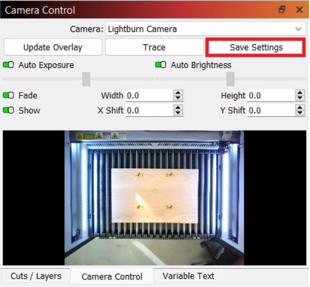
Select Lightburn Camera or Aeon Camera from dropdown > Save Settings
NOTE: This is not necessary for most users, but Lightburn has a bug for some that fails to save the calibration. If this is happening to you, save the settings as instructed above to resolve. You may also need to update your Lightburn software to the most recent version.
If you have any questions or concerns, please send us an email at support@aeonlaser.us for the fastest service. If your laser is malfunctioning, please submit a support ticket.
Happy Lasering!


