-

Getting Started 16
-

Maintenance 14
-

Troubleshooting 14
-

Repair 8
-

Laser 101 3
-

Materials 10
-

Accessories 20
-

Multi-Roller 7
-

LightBurn 9
Multi Roller Setup MIRA7


What You Need
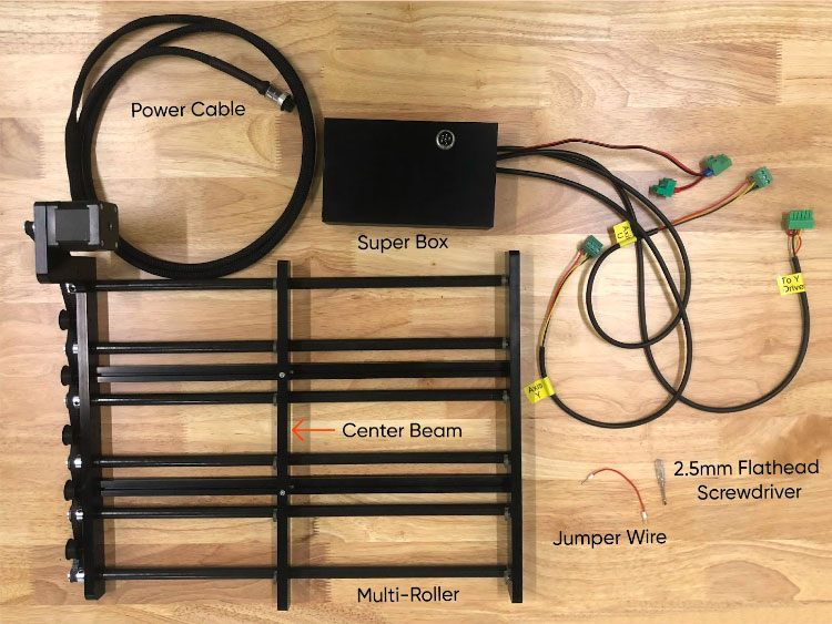
- Multi-Roller
- Supplied Jumper Wire
- Cabinet Key
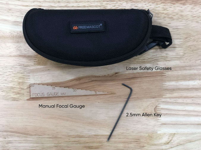
- 2.5mm Flathead Screwdriver
- 2.5mm Allen Key
- 20.5mm Manual Focal Gauge
- Laser Safety Glasses
Need assistance?
Book time with a qualified technician and unlock the potential of your Multi-Roller.
Steps
☠️ Warning ☠️ Turn OFF and unplug the power cord from the rear of the machine before starting.
Lay out the Multi-Roller and the Super Box to identify the parts using the diagram below.
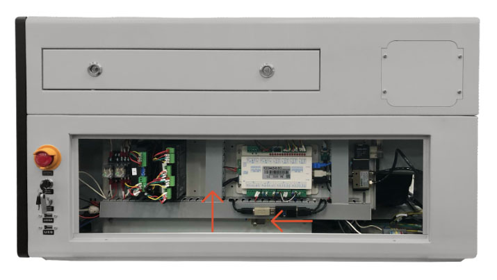
- Using the supplied cabinet key, remove the lower access panel on the right side of the machine. Set the panel aside.
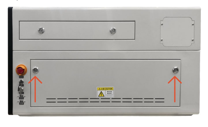
view of MIRA 7 side panel - Locate the drivers. (The black boxes located in the left hand side of the cabinet.) Determine if your machine has a 2- or 3-Driver Setup.
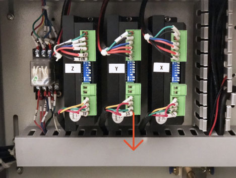
2-Driver Setup
2-Driver Setup 3-Driver Setup
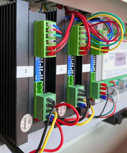
3-Driver Setup - Locate the wire cover between the drivers and the controller. Use this wire cover as a guide for where to position the Multi-Roller Super Box in the cabinet.
Wire cover between the drivers and the controller On the MIRA7, the plug port will not line up with the center of the wire track, due to the location of the 2-way solenoid.
- Remove the lower wire track cover in order to place the Super Box on the floor.
Wire track Note: When the wire track cover is removed, if the USB hub pops off, allow the USB hub and wires to gently hang in the cabinet while you complete the next steps. After the Super Box is fully installed, simply pop the USB hub back into place after the wire track cover is replaced.
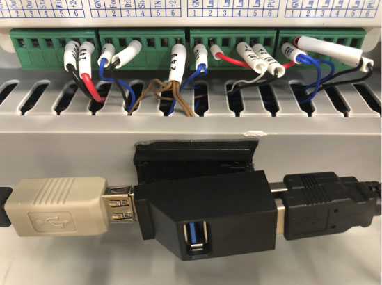
USB hub - The 2-way solenoid in the MIRA7 will be positioned in two different locations depending on what generation laser you have. Place the Super Box as close to the center wire track as possible.
Gen 1 MIRA7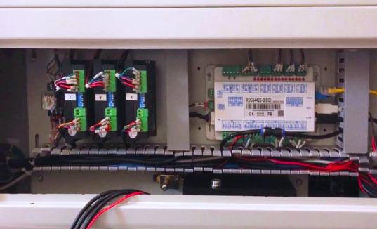
Gen 1 MIRA7
Gen 2 MIRA7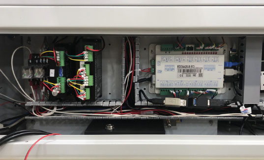
Gen 2 MIRA7 - Once you have found the correct location for the Super Box, remove it from the cabinet and unpeel the double sided tape. Replace it in the cabinet and push down on the Super Box to affix it to the floor.
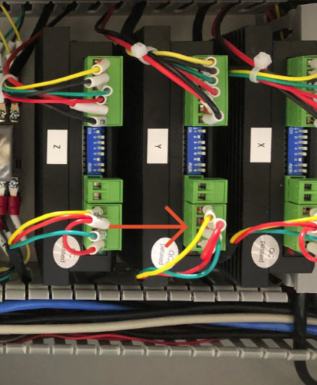
- Locate the Drivers.
For a 2-Driver Setup
- Locate the XY Driver on the 2-Driver Setup. Locate the green terminal block at the bottom of the driver.
XY Driver on the 2-Driver Setup - Remove the block from the driver. Be careful not to pull out any wires. Allow the terminal block to hang in place.
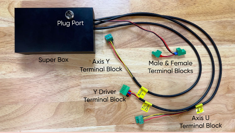
- On the Super Box, locate the wire with the Y Driver terminal block. Plug it into the empty Y Driver port in the cabinet.
Y Driver terminal block from Super Box to empty Y Driver port
For a 3-Driver Setup
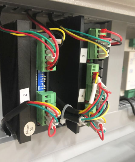
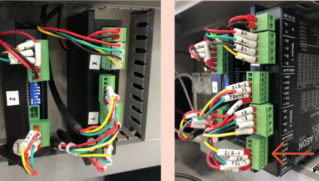
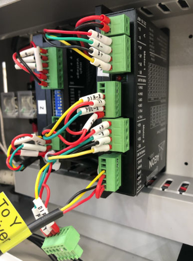
- Locate the Y Driver on the 3-Driver Setup. Locate the green terminal block at the bottom of the driver.
Y Driver on the 3-Driver Setup - Remove the block from the driver. Be careful not to pull out any wires.
- Using the supplied screwdriver, loosen each of the screws on the terminal block until you can remove the wires. Set the empty terminal block aside.
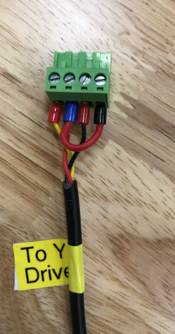
Loosen screws on the terminal block and remove the wires - On the Super Box, locate the wire with the Y Driver terminal block. Plug it into the empty Y Driver port in the cabinet.
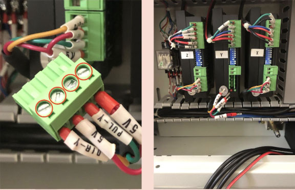
- Use your phone to take a photo of the Super Box Y Driver terminal block to use as reference. Note: This terminal block will have 6 screws.
Super Box Y Driver terminal block - Using the supplied screwdriver, loosen each of the screws on the terminal block until you can remove the wires.
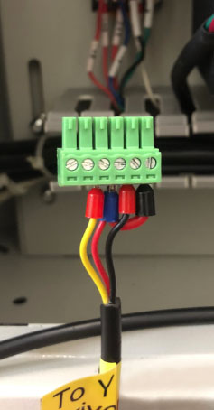
Loosen screws on the terminal block - Using the photo as reference, place the wires from the Super Box into the empty ports on the original terminal block that was removed from the machine driver (Note: This terminal block will have 4 screws). Ensure the ferrule connectors are in the correct order and are fully seated in the terminal port. Tighten the screws.
Note: This terminal block will have 4 screws - Plug the terminal block into the empty Y Driver port in the machine.
- Locate the XY Driver on the 2-Driver Setup. Locate the green terminal block at the bottom of the driver.
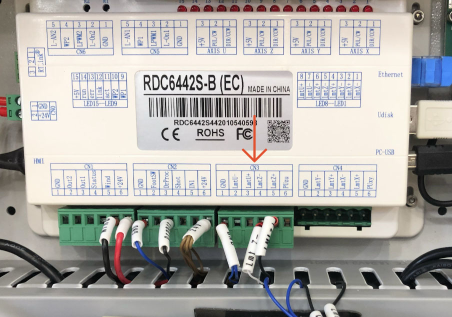
- Locate the Controller. Locate the CN3 and CN4 terminal blocks. Check to see if there is a jumper wire that runs between the two terminals. If there is, skip to step 21. If there is not a jumper wire, proceed to step 9.
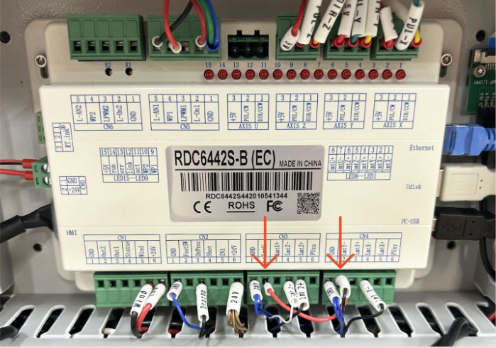
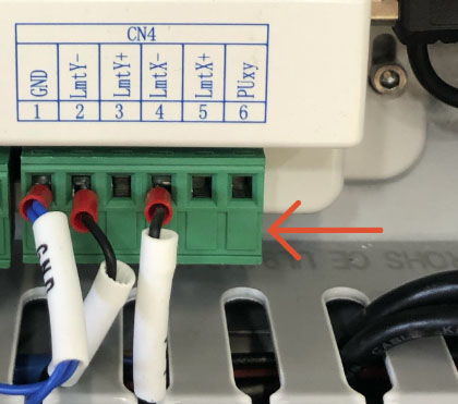
Jumper wire between CN3 and CN4 terminal blocks - Locate the Controller. Locate the CN4 terminal block.
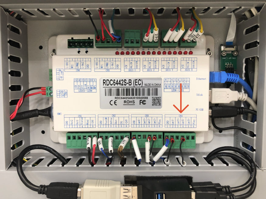
CN4 terminal block - Grabbing the green terminal block’s right side, gently pull the block away from the Controller. Be very careful not to pull on the wires.
CN4 terminal block - Spin the white wire labels so that you can read them all clearly.
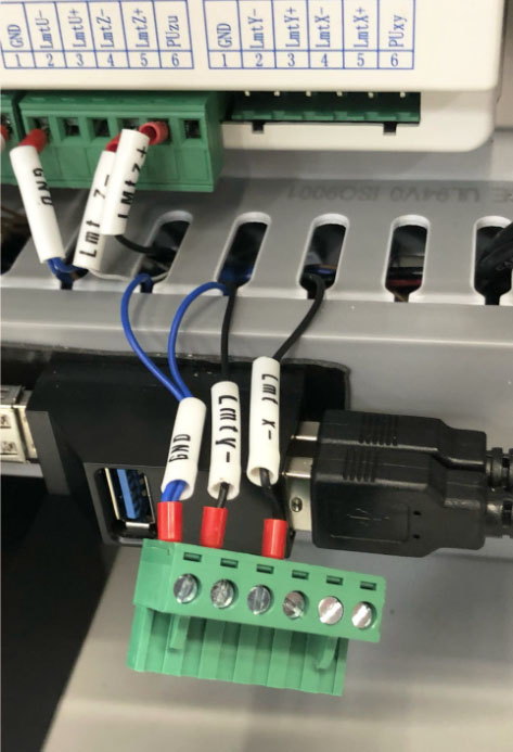
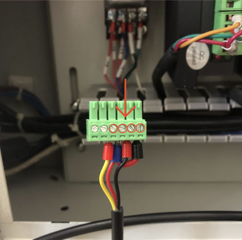
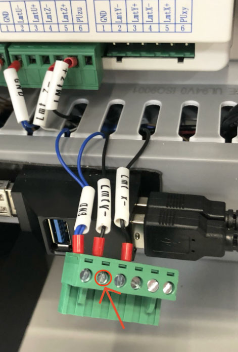
White wire labels - Using the supplied screwdriver, loosen the screw at the LMT Y- Terminal Port, approximately 5-6 turns.
Screw at the LMT Y- Terminal Port - Keep the existing wire in the terminal port and insert the ferrule connector of the provided jumper wire into the terminal port with the LMT Y- wire. Make sure both ferrule connectors are fully seated in the terminal port. Tighten the screw, and allow the terminal block to hang while you proceed to the next step.
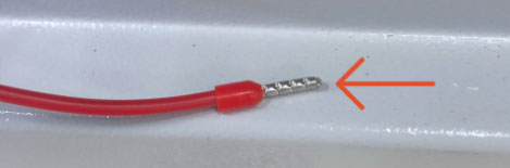
Ferrule connector 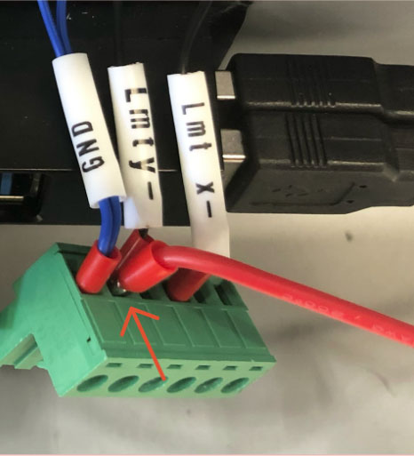
Both ferrule connectors fully seated in the terminal port - Locate the CN3 terminal block.
CN3 terminal block - Grabbing the green terminal block’s right side, gently pull the block away from the Controller. Be very careful not to pull on the wires.
- Spin the white wire labels so that you can read them all clearly.
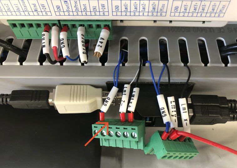
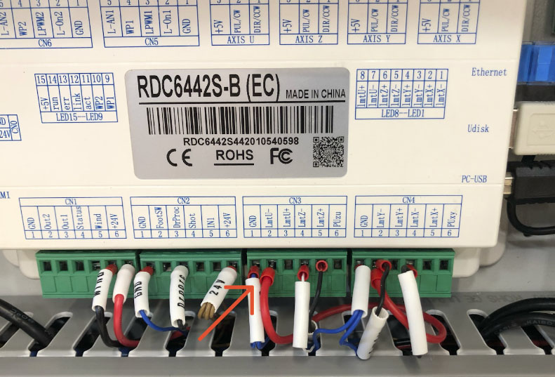
White wire labels - Using the supplied screwdriver, loosen the screw at the empty LMT U- port directly next to the GND wire, approximately 5-6 turns.
- Insert the other end of the jumper wire into the empty port, ensuring the ferrule connector is fully seated in the terminal port. Tighten the screw.
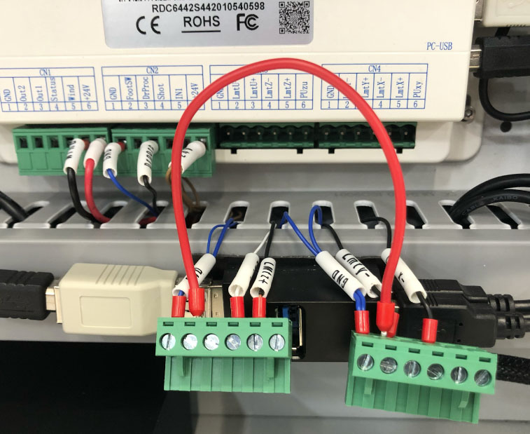
Jumper wire into the empty port - Plug the CN3 terminal block back into the Controller.
- Plug the CN4 terminal block back into the Controller.
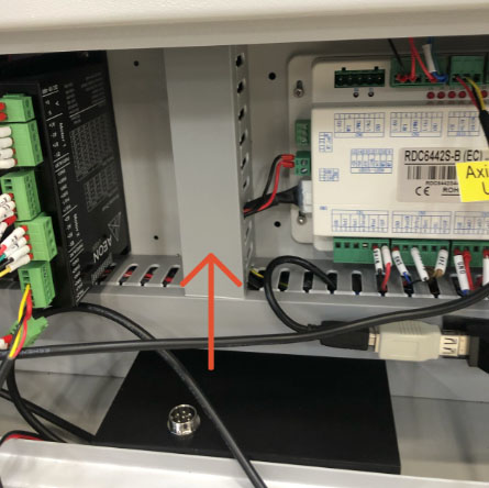
Controller with CN3 and CN4 terminal block plugged in - Locate the AXIS Y terminal block at the top of the Controller. Carefully pull the block from the Controller and allow it to hang in place.
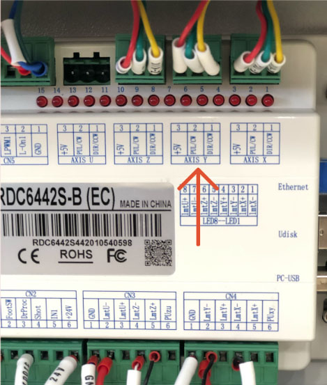
AXIS Y terminal block - Locate the AXIS Y terminal block attached to the wire leaving the Super Box, and plug it into the AXIS Y port.
- Locate the AXIS U terminal block at the top of the Controller. Carefully pull the block from the Controller and place it in your laser tool kit.
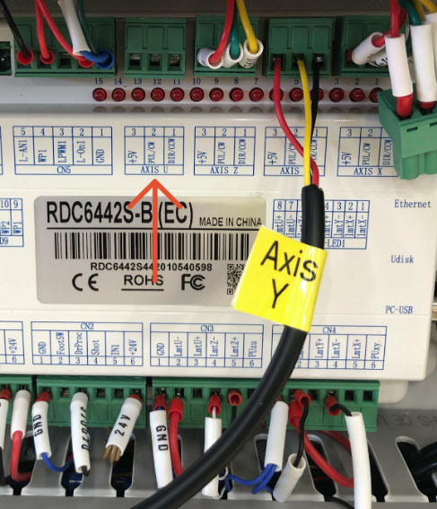
AXIS U terminal block - Locate the AXIS U terminal block attached to the wire leaving the Super Box, and plug it into the AXIS U port.
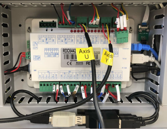
AXIS U terminal block into AXIS U port - Locate the wire track between the Controller and the driver. Remove the track cover and set it aside.
Wire track - Locate the CN0 terminal block on the left of the Controller.
- Carefully pull the CN0 terminal block away from the Controller. Be very careful not to pull on the wires.
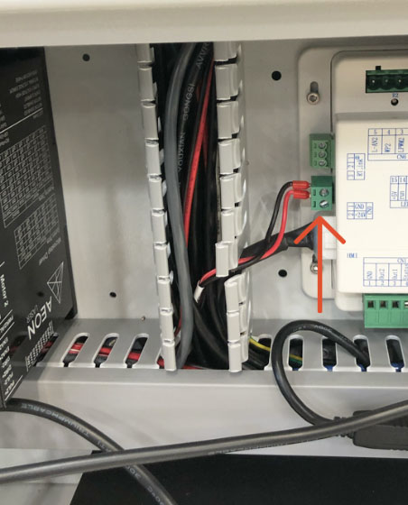
CN0 terminal block - Locate the Super Box wire with the male and female green terminal blocks.
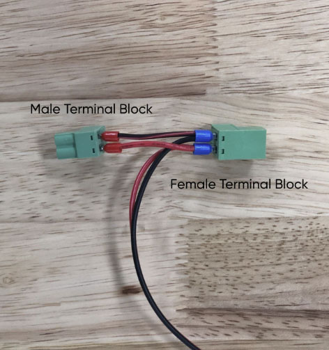
Male and female green terminal blocks - Plug the male terminal block that was removed from the CN0 terminal port into the female terminal block at the end of the wire leading from the Super Box.
- Plug the male terminal block leading from the Super Box into the CN0 terminal port.
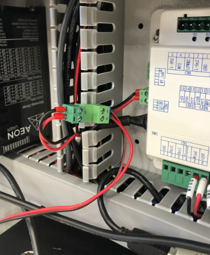
Male terminal block from Super Box into CN0 terminal port - Carefully tuck the wires leaving the Super Box behind the box on the floor at the back of the cabinet or feed them into the wire tracks.
- Replace the wire track covers.
- If the USB hub popped off the lower wire track cover when it was removed, push it back onto the base to secure it in place.
- Leave the cabinet open.


