-

Getting Started 16
-

Maintenance 14
-

Troubleshooting 14
-

Repair 8
-

Laser 101 3
-

Materials 10
-

Accessories 20
-

Multi-Roller 7
-

LightBurn 9
EMP Fiber Laser Auxiliary Package Installation


Overview
What you will learn
In this guide, you will learn how to wire and install the exhaust fan and task light for an EMP Fiber Laser.
When to do this
The EMP Fiber Laser auxiliary package is designed to extract fumes produced during engraving with the Fiber Laser, while enhancing visibility by illuminating the work area. These innovative accessories seamlessly integrate by plugging into the back of any EMP Fiber Laser, ensuring convenient operation.
What you need
- Fan and Light Installation Kit
- Allen Key Set (comes with machine)
- #2 Phillips Head Screwdriver
- Wire Snips
- Wire Strippers
Need assistance?
Book time with a qualified technician and get help setting up the Fiber Auxiliary Kit.
Wiring Procedure
NOTE: If your machine already has the relay installed and wired, skip the Wiring Procedure and proceed to the Fan and Light Mounting Procedure.
- Power OFF and unplug the machine.
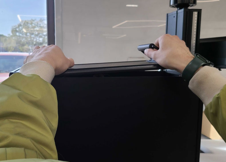
- Use a 5 mm Allen key to remove the top plate mounting bolts (6). Keep these bolts safe as you'll need them for reassembly.
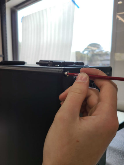
- Remove the top cover plate along with the serial number side panel. Place them aside in a safe location.
- Remove the two elongated wire track covers and set them aside in a safe spot.
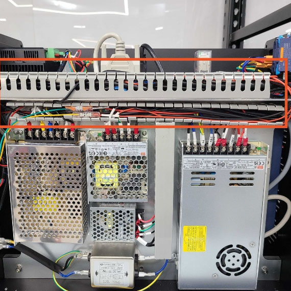
- Retrieve the pre-wired relay from your auxiliary kit, then remove the protective covers from the adhesive tape on the back of the relay.
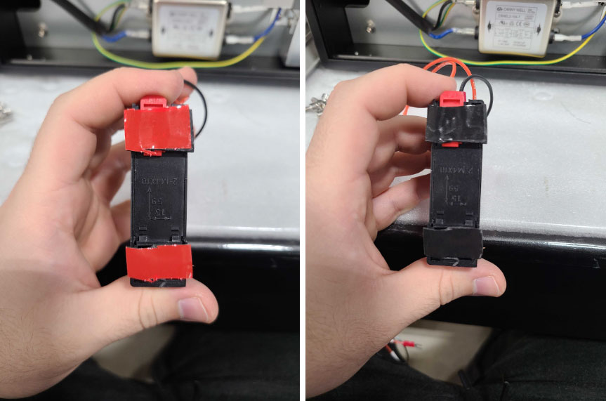
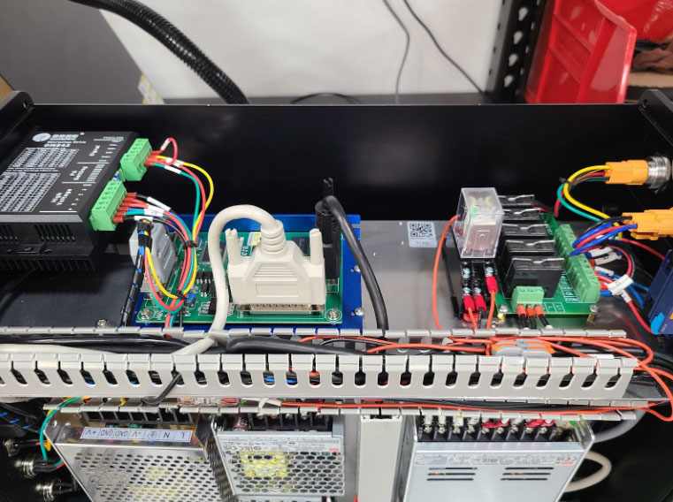
- Securely attach the relay inside the machine on the top plate, near the controller and relay boards. Press firmly to ensure the adhesive tape fully adheres.
NOTE: Depending on your machine's model, position the relay to the left or right side of the controller board.
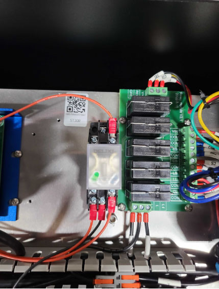
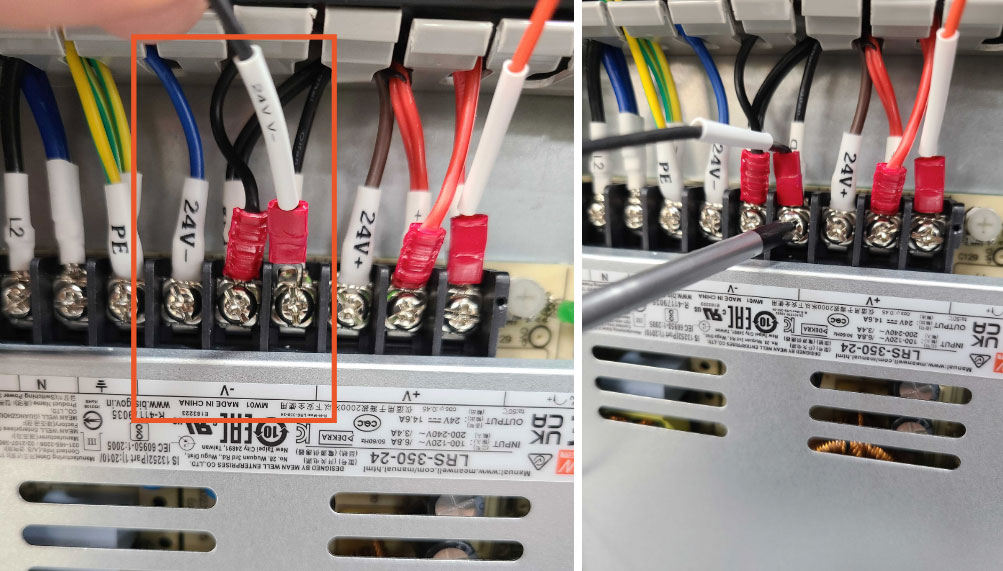
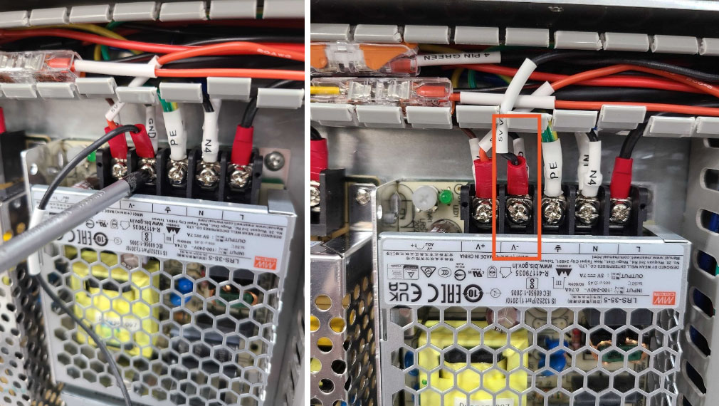
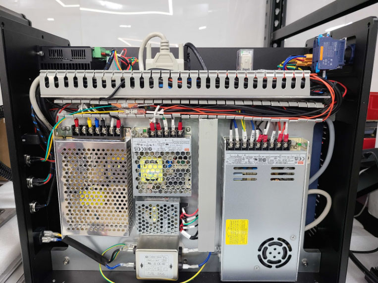
- Locate and identify the 24V PSU.
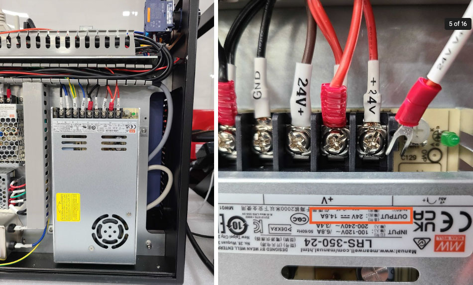
- Locate the wire labeled “24V V+” from the relay, as well as the “V+” ports on the PSU. Use a Phillips head screwdriver to mount the wire into the far right “V+” port on the PSU.
NOTE: The port will have a wire connected to it already. Stack the new wire on top of the installed wire. Ensure both are seated fully before securing.
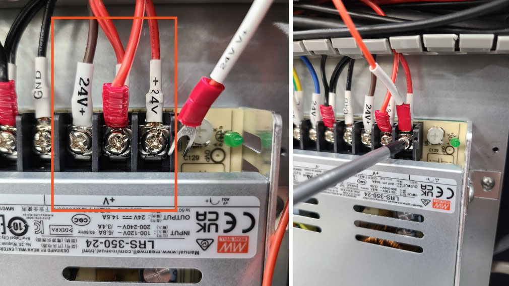
- Locate the wire labeled “24V V-” from the relay, as well as the “V-” ports on the PSU. Use a Phillips head screwdriver to mount the wire into the far right “V-” port on the PSU.
NOTE: The port will have a wire connected to it already. Stack the new wire on top of the installed wire. Ensure both are seated fully before securing.
- Locate and identify the 5V PSU.
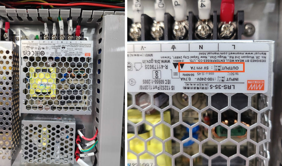
- Locate the wire labeled “5V V+” from the relay, as well as the “V+” port on the PSU. Use a Phillips head screwdriver to mount the wire into the “V+” port on the PSU.
NOTE: The port will have a wire connected to it already. Stack the new wire on top of the installed wire. Ensure both are seated fully before securing.
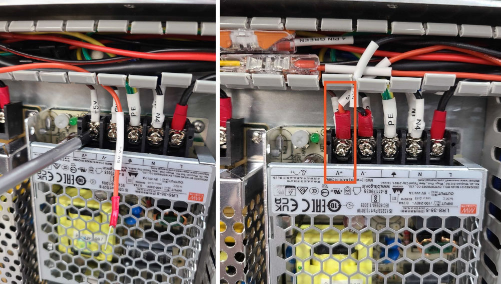
- Retrieve the black wire from the kit that has the fork and lever connector installed.
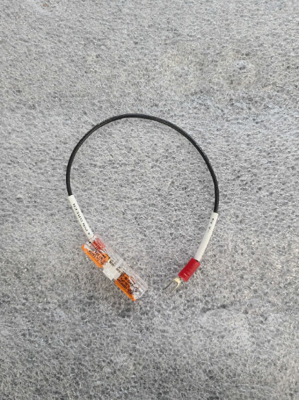
- Use a Phillips head screwdriver to mount the forked end of the wire into the “V-” port on the 5V PSU.
NOTE: The port will have a wire connected to it already. Stack the new wire on top of the installed wire. Ensure both are seated fully before securing.
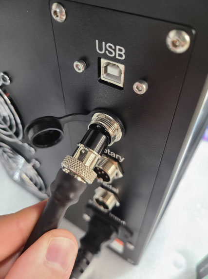
- Locate the 4 pin connector on the rear of the machine, as well as the green and yellow wires coming from the back of the connector.
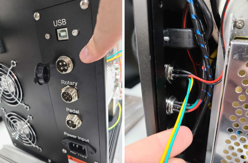
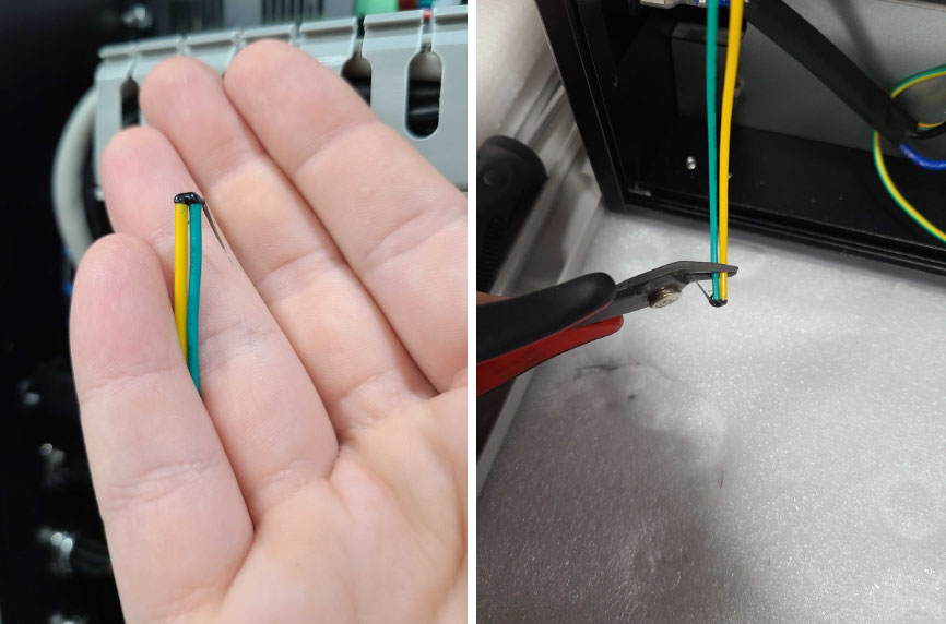
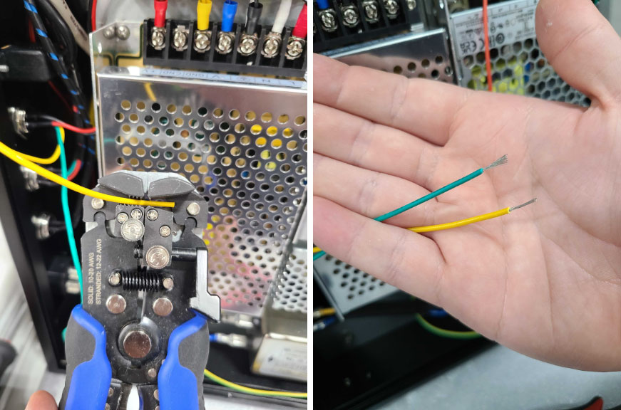
- Free the green and yellow wires from their track and trim any sealant at the ends. Strip approximately half an inch of sheathing off each wire and twist the exposed wires tightly.
- Insert the end of the yellow wire into the clip connector on the remaining relay wire labeled “4 PIN YELLOW”. Flip the lever down to secure the wire, and lightly tug to ensure it is seated properly.
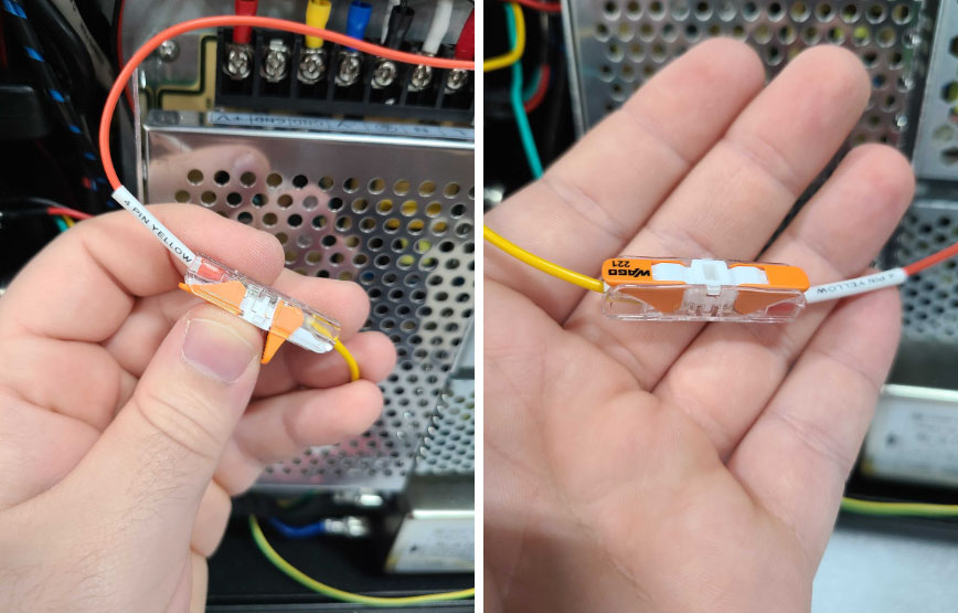
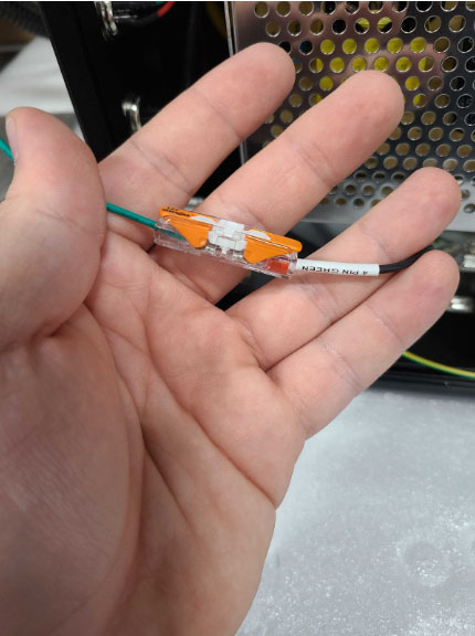
- Insert the end of the green wire into the clip connector on the remaining wire labeled “4 PIN GREEN”. Flip the lever down to secure the wire, and lightly tug to ensure it is seated properly.
- Carefully arrange all wires within the wire tracks for a neat setup. Reattach the wire track covers.
- Ensure the relay block is fully engaged by pressing down on the top of the clear portion.
- Reinstall the side panel and top cover back onto the machine.
Fan and Light Mounting Procedure
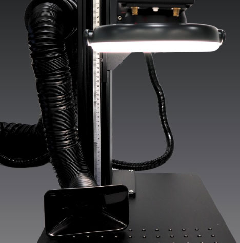
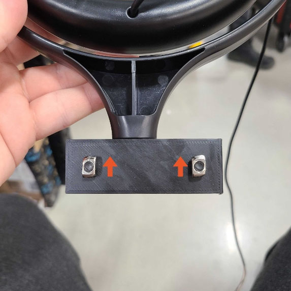
- Retrieve the task light and orient it so you are able to access the mounting locks on the light mount. Spin the T slot nut mounting tabs so they are sitting vertically as pictured below.
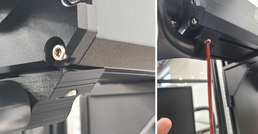
- Insert the T slot nuts into the channels under the laser arm. Pull the light so it is mounted around and as close to the lens as possible, then use a 4 mm Allen key to secure the light to the laser arm.
- Guide the light's wire along the side of the arm, letting the excess cable hang behind the machine temporarily.
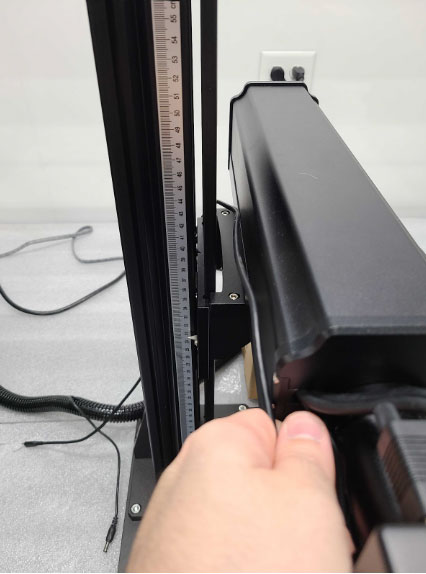
- Retrieve the fan mount and install it onto the lowest available slot on the left side of the laser arm mast by spinning the threaded standoff into the appropriate slot. Orient the mount so it is sitting vertically.
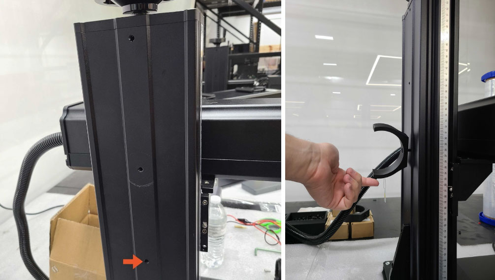
- Gently push the exhaust fan into the fan mounting bracket. It should lightly click into place.
NOTE: Ensure the fan wire is behind the clamp for the most secure seating possible.
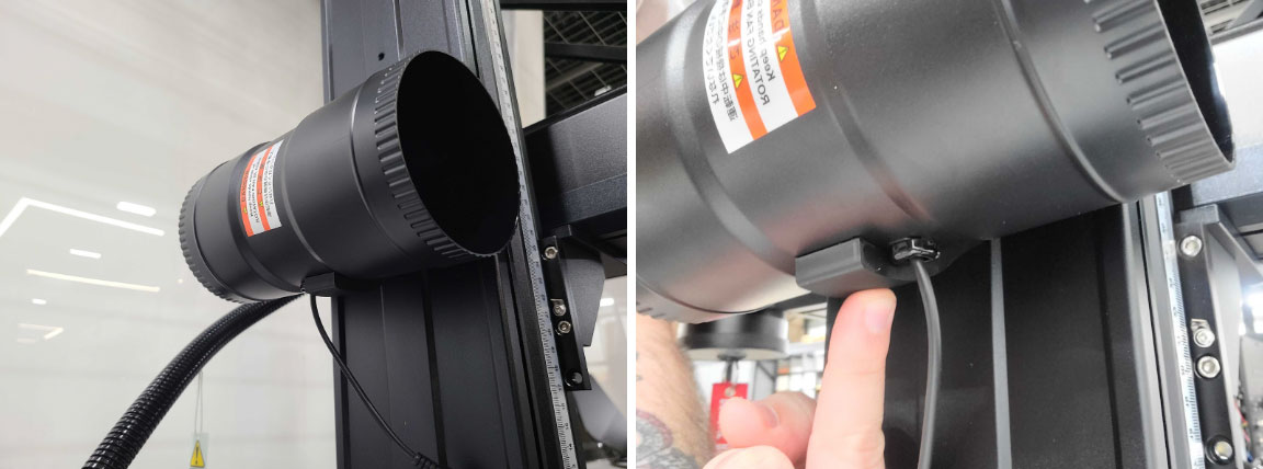
- Retrieve the power cable from the kit and attach it to the 4 pin connector on the rear of the machine.
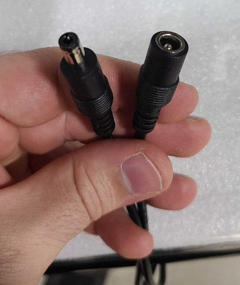
- Connect both the task light and the exhaust fan to their designated power ports. These components are designed to fit only their respective ports, ensuring a correct connection.
- Attach the exhaust hose to the back of the exhaust fan using one of the hose clamps provided in the kit. Direct the hose towards your desired fume extraction point. Secure the hose to this exit port with the remaining hose clamp, completing the installation.
If you have any questions or concerns, please send us an email at support@aeonlaser.us for the fastest service. If your laser is malfunctioning, please submit a support ticket.
Did you find this document helpful? Let us know what you liked or what we can improve on by sending an email to helpusgrow@aeonlaser.us.
Happy Lasering!


