-

Getting Started 16
-

Maintenance 14
-

Troubleshooting 14
-

Repair 8
-

Laser 101 3
-

Materials 10
-

Accessories 20
-

Multi-Roller 7
-

LightBurn 9
External Air Compressor


Why use an Air Compressor?
Using an external air compressor with a CO2 laser has its advantages, although it is not essential. One of the main benefits is that it provides cleaner cuts on a wide range of materials. Additionally, it tends to increase cutting speeds and reduces the need for masking on wood and acrylics.
Smart Solenoid
The Aeon MIRA Pro is the only laser on the market that includes a smart solenoid. This solenoid has a unique feature that allows it to switch between low pressure (using the built-in air pump) and high pressure (using an external air compressor) within the LightBurn software. By simply toggling the "Air Assist" option, users can switch between the two modes seamlessly.
The smart solenoid also includes a safety mechanism that automatically reverts to the internal air pump in case of an external air compressor failure. This safety feature minimizes the risk of encountering zero air supply during a cutting operation in most situations.
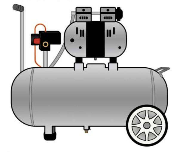
California Air Compressor Setup
While it is not possible to cover all the different compressor setups due to the numerous variables involved, we can provide guidance for installing the California Air 8-gallon unit.
What You Need
- External Air Compressor
- Water Separator
- Black Air Hose with 1/4" NPT Fitting
- Pliers
- 14mm Wrench
Steps
- Set up the external air compressor, following included instructions.
California Air Compressor - Put together the water separator:
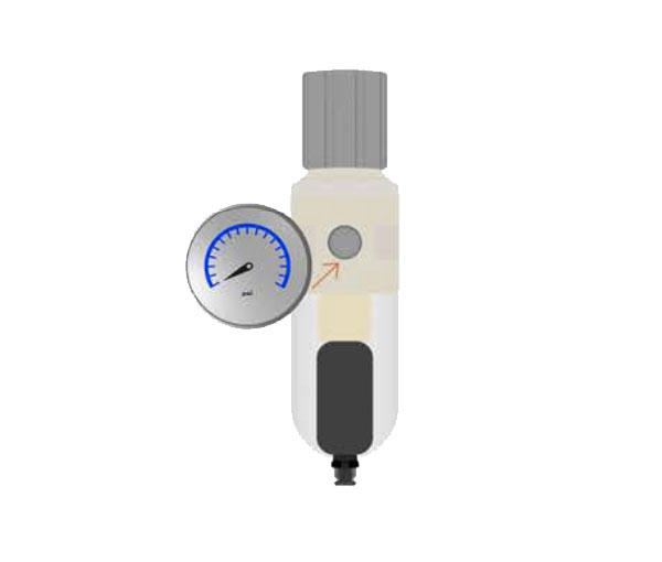
- Cut 2-3" of thread seal tape and wrap it clockwise around the threaded portion of the gauge 3-4 times, ensuring the holes are not covered at all by the tape.
2-3 inches of thread seal tape wrapped around the threaded portion of the gauge - Twist the threaded fitting of the water separator gauge into the 1/8" NPT fitting on the front of the regulator body, you may need to remove a red, plastic piece from the opening before you are able to do so. Hand screw in tight and ensure that the top of the gauge is vertical with the body of the water separator.
Water separator - Cut two 2-3" long pieces of thread seal tape and wrap it clockwise around the threads on both sides of the 1/4" barbed brass fitting, ensuring the holes are not covered at all by the tape.
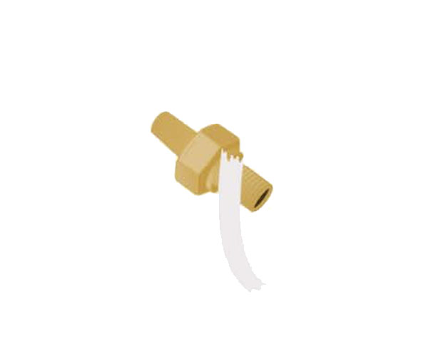
Thread seal tape around 1/4" barbed brass fitting - Hand screw one end of the barbed brass fitting into the water inlet opening on the regulator body, ensuring there is no teflon tape inside of the fitting. You may need to remove a red, plastic piece from the opening before you are able to do so.
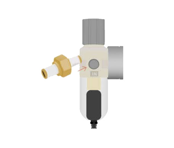
Screw barbed brass fitting into water inlet - Using a 14mm wrench, tighten the barbed brass fitting.
- Unscrew the filter cup and set aside.
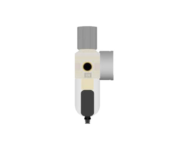
Filter cup is located on the bottom of the water separator
- Cut 2-3" of thread seal tape and wrap it clockwise around the threaded portion of the gauge 3-4 times, ensuring the holes are not covered at all by the tape.
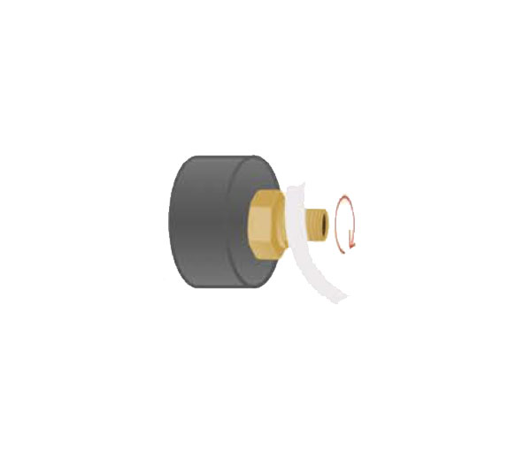
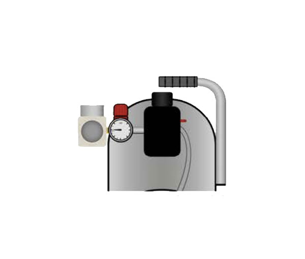
- Using pliers, remove the brass quick release on the air compressor. Be sure to have one hand on the red regulator, holding firmly, to ensure that it does not move as you remove the brass fitting.
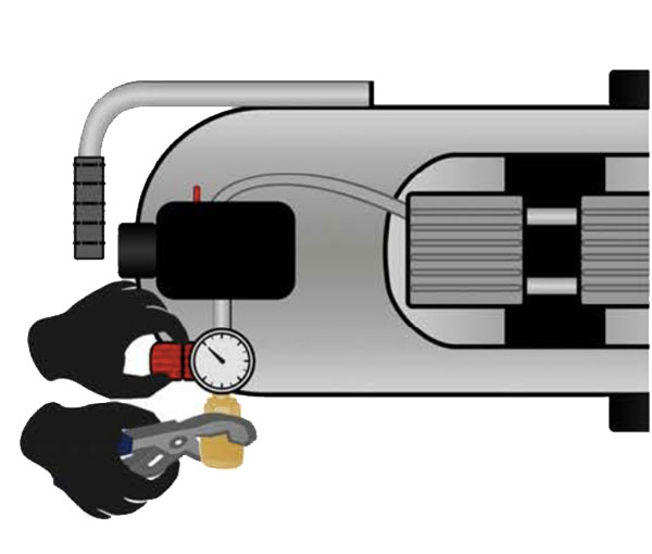
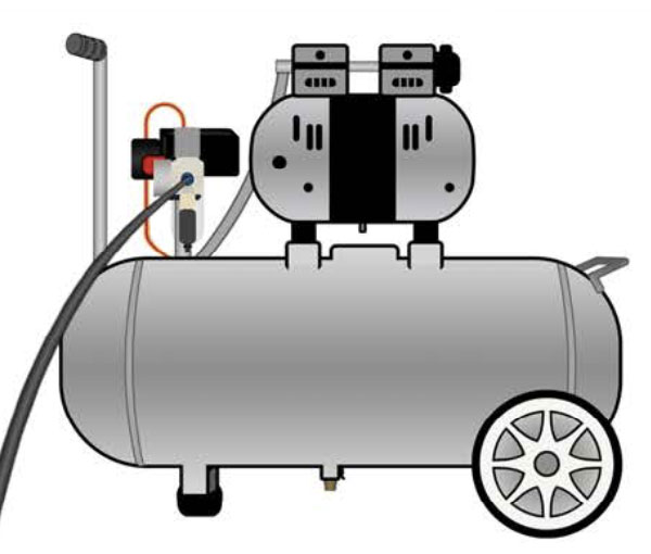
Using pliers, remove the brass quick release on the air compressor. - Carefully hand screw the barbed brass fitting on the water separator inlet into the threaded opening on the air compressor. Use a wrench to ensure that it is fully tightened, with the pressure regulating knob positioned on top.
Hand screw the barbed brass fitting on the water separator inlet into the threaded opening on the air compressor - Re-screw the filter cup to the body of the regulator body so that it is positioned below the regulating knob. You may need to adjust the position of the water separator so that the filter body remains vertical.
Front view of compressor with filter cup re-connected to body of the regulator body - Inside the clear tote that came with your laser, you will find a length of black hose and a 1/4" NPT to 6mm fitting. These components are necessary for connecting the compressor to the back of your laser.
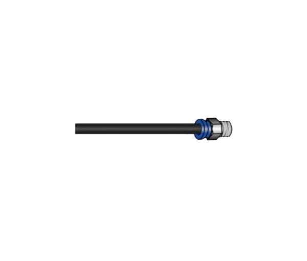
Black hose with 1/4 inch NPT to 6mm fitting - Push the end of tube into BLOWING opening located on the back of the laser.
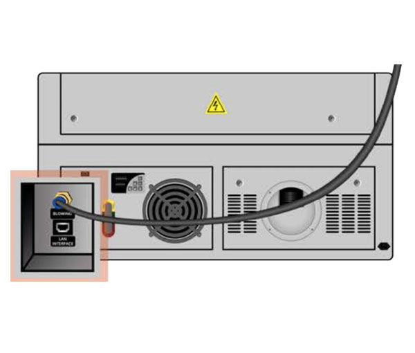
BLOWING opening located on rear of laser Note: You do not need to open the laser side panels, simply plug in the black hose into the rear of the laser.
- Screw the other, threaded end into the outlet opening on the regulator body.
Hose connected to outlet opening on the regulator body - Plug the air compressor into an outlet.
- Turn the air compressor on and allow it to run for 3-5 minutes.
- Adjust the pressure gauges:
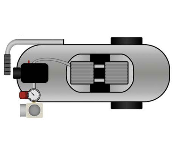
- The tank pressure gauge should read 120psi.
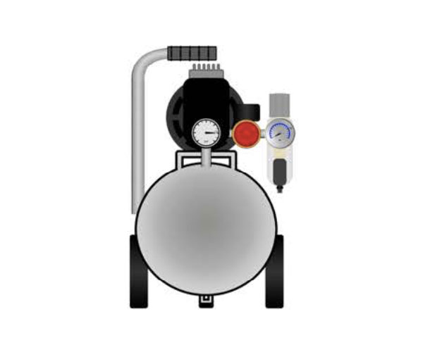
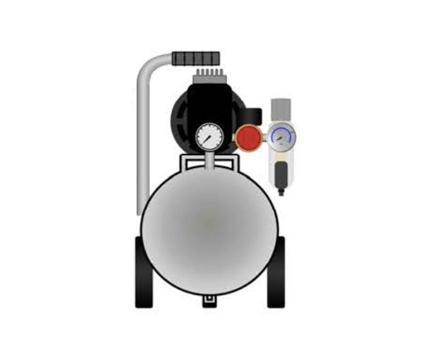
Tank pressure gauge located on front of air compressor - The red cap gauge should read 120 psi. You may need to adjust the red cap gauge pressure. Ensure it is screwed in all the way so it is tight.
Overhead view of air compressor and red cap gauge - The water separator gauge should read 15-40psi. To adjust the water separator gauge pull the gray cap up, you'll hear a click, turn it clockwise until you reach the optimal pressure.
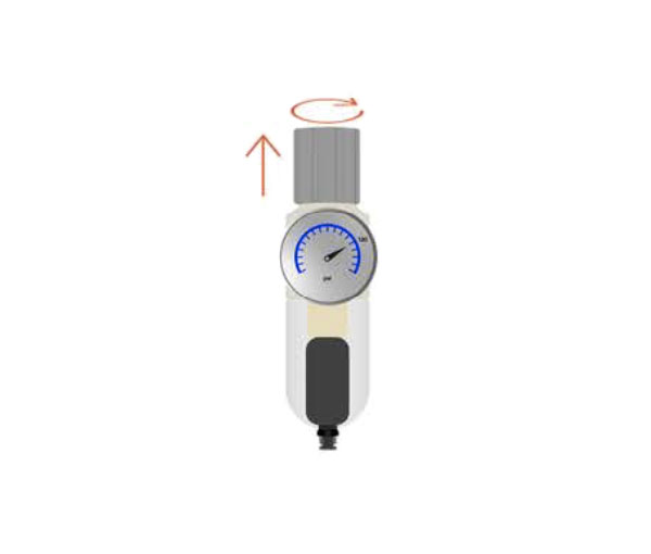
Water separator
- The tank pressure gauge should read 120psi.
- Once you are done using the external air compressor, be sure to turn it off, unplug, and drain the moisture.


