-

Getting Started 16
-

Maintenance 14
-

Troubleshooting 14
-

Repair 8
-

Laser 101 3
-

Materials 10
-

Accessories 20
-

Multi-Roller 7
-

LightBurn 9
Smart Rotary - MIRA Pro


Overview
What you will learn
In this guide, you will learn how to install and use the Smart Rotary with your MIRA.
When to do this
The Smart Rotary is designed to be used when trying to engrave cylindrical or rounded objects. It allows the machine to engrave or mark around the circumference of cylindrical items such as cups, glasses, bottles, or other similar objects.
What you need
- Smart Rotary
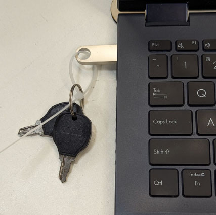
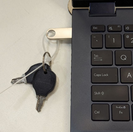
- USB drive that came with the machine (attached to machine ignition key)
- 20.5 mm Focus Gauge
- 2.5 mm Allen Key
- Cabinet Key
- Laser Safety Glasses
Need assistance?
Book time with a qualified technician and learn how to install and optimize your rotary attachment.
Video
Smart Rotary Setup
- Lift the machine lid and remove all contents sitting atop the honeycomb. Carefully remove the honeycomb and set it aside in a safe location.
NOTE: Avoid standing the honeycomb upright, against a corner, or in a similar position that could lead to damage.
- Power ON the machine and allow it to fully reset.
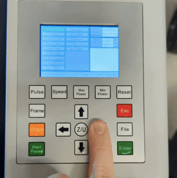
- Press the “Z/U” button on the keypad so that “Z Move” is highlighted. Then, press and hold the “RIGHT” arrow key until the table lowers fully.
- Press “ESC” to the exit menu.
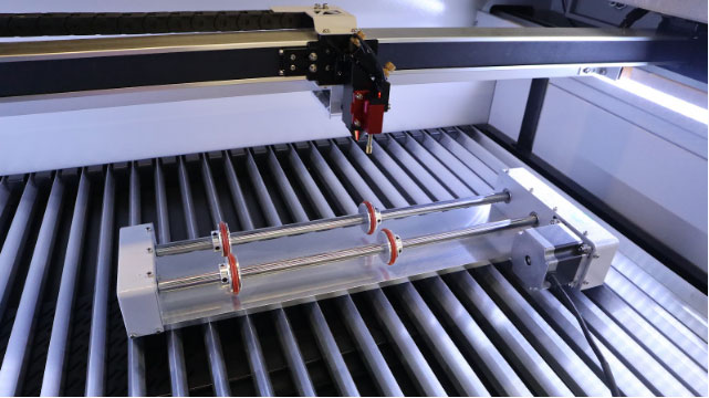
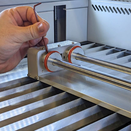
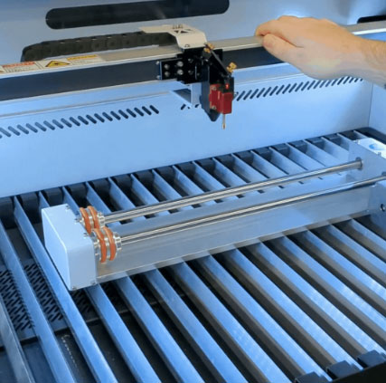
- Carefully place the rotary onto the center of the machine bed, ensuring that the motor faces to the right once inside (as relative to the front of the machine). With the Smart Rotary unplugged, manually spin the rollers until the set screws on the wheels are facing upwards.
- Use a 2.5 mm Allen wrench to loosen the set screws on all four wheels.
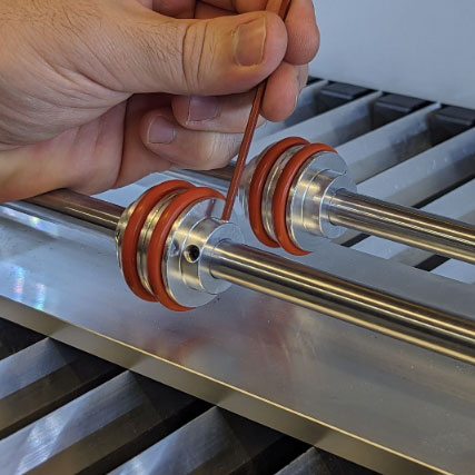
NOTE: Only loosen the set screws by 2-3 turns, until the wheels can slide freely along the rollers. Do not completely remove them.
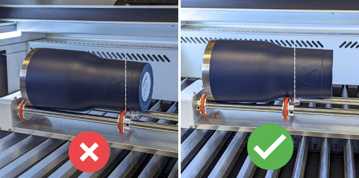
The size and shape of the workpiece will determine how to adjust the wheels. Ensure that any bumps, ridges, or raised logos on the surface of the workpiece are not in the direct path of the wheels.
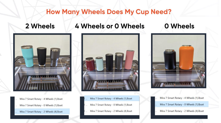
Identifying the Appropriate Rotary Settings
Different types and styles of cups will require different rotary settings to be loaded. For example, a tumbler with a sharp taper from base to mouth will require a different set up to get the engraving surface level versus a perfectly cylindrical cup. It is important to identify what the proper settings and rotary setup is needed before moving forward. The following are the settings that are appropriate for different cup/cylinder styles and types when engraving with the Smart Rotary.
For the purpose of this guide, we will be using a 2 Wheel setup. If the item you wish to engrave would require a different setup, here is how to identify which to use.
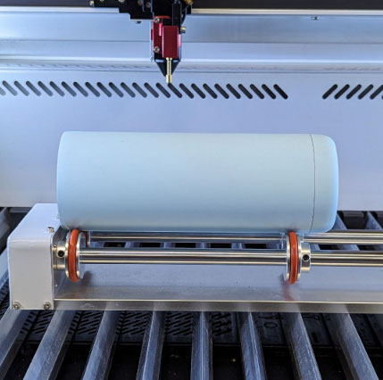
4 Wheel Setup
The 4 wheel setup is ideal for perfectly cylindrical workpieces, where it will rest on all four wheels and remain level.
- Slide the left 2 wheels to the left end of the rotary, away from the motor. Adjust the spacing as you place the workpiece onto the wheels.
NOTE: Having the wheels too tightly pressed into the rotary wall may lead to seizing or binding. Leave a small gap between the wheel and the wall if you experience this.
- Position the mouth of the workpiece towards the wall of the rotary to prevent shifting, but do not allow the workpiece to touch the frame of the rotary. A small gap should remain, just wide enough to slide a piece of paper in, to help prevent binding. Continue adjusting the wheels until the weight of the cylinder is evenly distributed.
- Once all 4 wheels are in position, use a 2.5 mm Allen wrench to tighten both set screws on all 4 wheels. Be careful not to overtighten. The wheels just need to be snug enough to keep from sliding out of position. If necessary, the cup can be removed for better access.
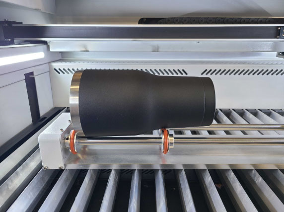
2 Wheel Setup
If the workpiece is not a perfect cylinder, you will need to use the 2 wheel setup to get the workpiece level. The widest end of the workpiece will sit directly on the metal rollers instead of on the other 2 wheels, like in the 4 wheel setup.
- Slide 2 of the wheels to the far end of the rotary, away from the motor. They should be positioned against the wall of the Smart Rotary.
NOTE: Having the wheels too tightly pressed into the rotary wall may lead to seizing or binding. Leave a small gap between the wheel and the wall if you experience this.
- Position the mouth of the workpiece directly on the metal bars and against the sides of the 2 farthest away wheels to prevent shifting. Adjust the remaining 2 wheels underneath the opposite end until the area to be engraved is level.
- Once all 4 wheels are in position, use a 2.5 mm Allen wrench to tighten both set screws on all 4 wheels. Be careful not to overtighten. The wheels just need to be snug enough to keep from sliding out of position. If necessary, the cup can be removed for better access.
0 Wheel Setup
If the cylinder is too large to sit atop all 4 wheels or seems unstable with a 4 wheel setup, try positioning the workpiece directly onto the metal bars. The wheels will serve to secure the workpiece to the rotary in this setup, rather than lay atop them.
- Slide the left 2 wheels to the left end of the rotary, away from the motor.
- Place the cup into the rotary and rest it directly on the bars of the rotary. Slide the right set of wheels towards the end of the cup. They will act as a rear clamp to help keep the cup from shifting while engraving.
NOTE: Having the wheels too tightly pressed into the rotary wall or cup may lead to seizing or binding. Leave a small gap between the wheel and the wall/cup if you experience this.
- Once all 4 wheels are in position, use a 2.5 mm Allen wrench to tighten both set screws on all 4 wheels. Be careful not to overtighten. The wheels just need to be snug enough to keep from sliding out of position. If necessary, the cup can be removed for better access.
Loading the Rotary Settings
- Plug the USB thumb drive that came with your laser into an open USB port on your computer.
- Connect your computer with Lightburn installed to the machine via your preferred method of connection. For this guide, a USB connection was used.
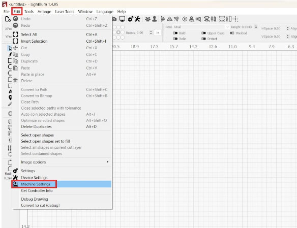
- In Lightburn:
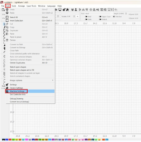
- Click on “Edit” along the top toolbar.
- Click on “Machine Settings”.
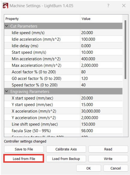
- In the “Machine Settings” window:
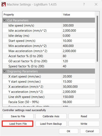
- Click “Load from File” on the bottom left portion of the window.
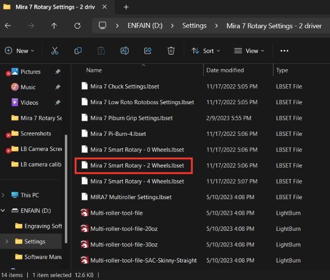
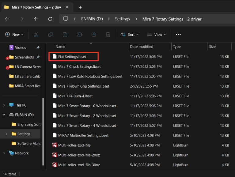
- Navigate to the machine USB in your file explorer.
- Open the “Settings” folder.
- Open the “Rotary Settings” folder and select the appropriate .lbset file as identified from the previous section.
- With the appropriate file selected click “Open”.
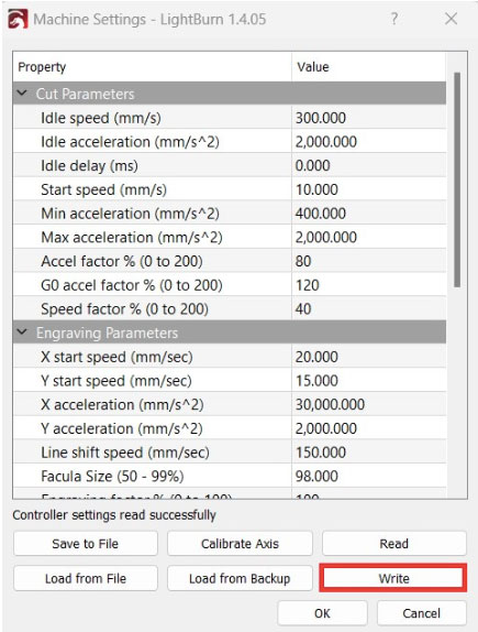
- Click “Write” to overwrite the settings to the controller.
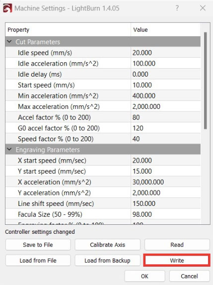
After the settings are written, there should be a small message near the buttons at the bottom of the “Machine Settings” window that says “Controller settings written successfully”. If there is a message saying “Communication with controller failed”, click “Read” towards the bottom right of the window, return to Step 4.1, and repeat the process.
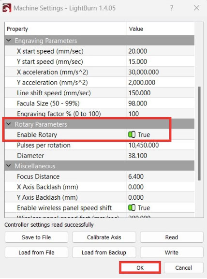
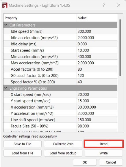
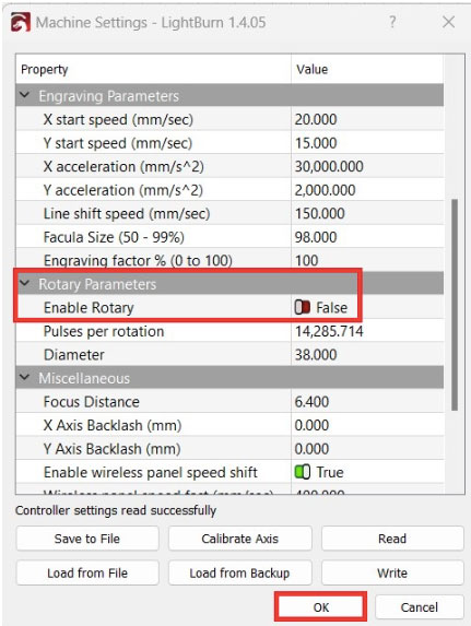
- Click “Read” after the settings are successfully flashed. Scroll down in the window to the “Rotary Parameters” section.
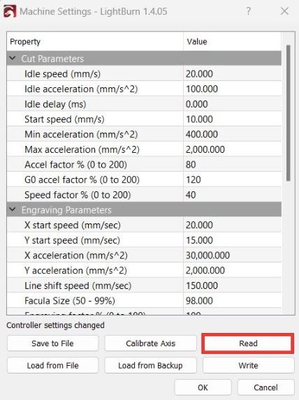
- Verify that “Enable Rotary” is set to “True”.
- Click “OK” on the “Machine Settings” window to close.
- Click “Load from File” on the bottom left portion of the window.
CAUTION: If the “Enable Rotary” setting is NOT set to “True”, that means the settings were not loaded properly. Return to Step 4.a and repeat the process.
Preparing a File in Lightburn
Loading a File
Any settings provided in this section are suggestions and serve as examples to help users get setup. You will have to do your own testing to determine the settings that best match your preferences.
“Open” or “Import” your design in Lightburn, and scale it to the appropriate size.
NOTE: In most cases, you will need to rotate the design so that it correlates with the way the workpiece is positioned inside the machine.
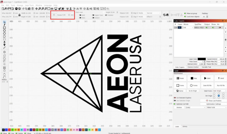
NOTE: To help with scaling your design, draw a rectangle in a different layer to represent the height and circumference of the available workspace. (Cir = Dia. x 3.14). Lightburn has a “Tool Paths” feature via the “T1” and “T2” layers found at the bottom layer of the “Selection” bar. These layers default to a “no output” setting and will only frame. If you use a regular layer, remember to delete it or toggle the Output “OFF” in the “Cut/Layers Window” before sending the file to the machine.
Cuts/Layers Settings
The following parameters are recommended and can be situated in the “Cuts/Layers Window” as desired. For the purpose of this guide, these are the settings that were used.
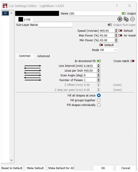
- In the Cuts/Layers section within Lightburn, select the “Fill” mode setting to engrave the design. “Line” mode would give an outlined result for the file. For this guide, “Fill” mode was used.
- A range of speeds from 100 mm/s to 700 mm/s is viable when using the rotary. Higher speeds can lead to wobbling or jittering while engraving. Adjust the speed to match the desired result. A speed of 400 mm/s was used for this guide.
- Adjust the power according to the material type, tube type, and tube wattage. For this guide, we used a power of 45% on a 60W glass CO2 tube. The material of the cup is powder coated aluminum. If working with glass, see our article surrounding glasswork.
- The Lines Per Inch (LPI) will change depending on the desired result and finish. An LPI between 250-400 is a good starting range, but LPI upwards of 700 to 800 may be necessary for smoothing the edges of curves in a design. An LPI of 400 was used for this guide.
- In the “Common” tab, select “Fill all shapes at once”.
- In the “Advanced” tab, make sure “Flood Fill” is toggled “OFF”NOTE: It is recommended for users to only use the internal air pump with their rotary. Ensure that “Air Assist” is toggled “OFF”.
- Click “OK”.
- In the Laser Window, set “Start From” to “User Origin” and select the center button for the “Job Origin”.
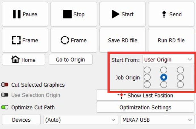
NOTE: To verify settings before sending the job to the machine, click “Window” > “Preview”, followed by the “Play” button. Make sure the entire job sweeps from front to back of the machine (bottom to top of the screen) in one fluid motion. Click “OK” once confirmed.
- In the “Laser” window, ensure you have a connection. It should say “Ready”.
NOTE: If it says “Disconnected”, make sure the laser is powered ON and connected to your computer via USB, Ethernet, or Wi-Fi. Then, reset the connection by right-clicking the “Devices button” in the “Laser” window.
- Click “Send”.
- Name the file.
- Click “OK”. The job is now saved into the machine’s memory.
Installing the Smart Rotary
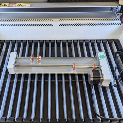
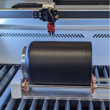
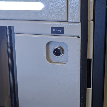
- Plug the rotary into the “Rotary Port” found at the front right-hand corner inside the machine.
- Carefully push or pull the gantry over the rotary by hand, such that the red dot is just hitting the edge of the rotary.
- Route any excess cable so that it is clear from the rollers, gantry, and laser head.
NOTE: Once the rotary is plugged into the machine, the “UP/DOWN” arrow keys will now control the rollers, NOT the gantry. Avoid pressing them at this time.
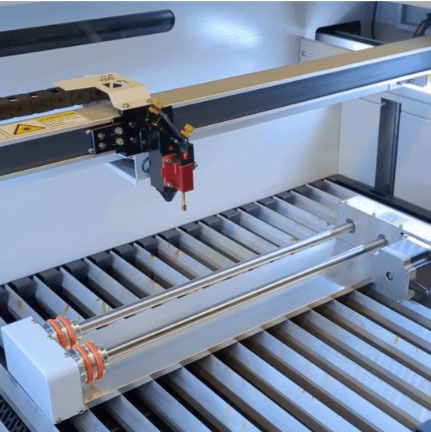
- To align the smart rotary to the gantry, the front edge of the silver baseplate can be used as a visual aid. Position the red beam from the laser head at the center of the baseplate edge.
NOTE: Be sure to adjust the rotary itself and to NOT move the gantry during this process.
- Using the “LEFT/RIGHT” arrow keys, jog the laser head to the far left side of the rotary and line up the front edge so that it’s perfectly underneath the red dot.
- Jog the laser head to the far right side. Watch to see if the red dot travels parallel across the entire front edge of the rotary.
- Adjust the Smart Rotary as needed. The Smart Rotary is aligned once you can jog the laser head along the entire front edge while maintaining the red dot parallel to it.
- Once the rotary is aligned, use the “UP/DOWN” arrow keys to spin the rollers until the Y coordinate on the keypad is reading approximately in the middle of the total possible travel distance.
The Y-coordinate on the keypad should read the following (+/- 5 mm):- 150 mm for MIRA5
- 225 mm for MIRA7
- 300 mm for MIRA9
Setting Up the Workplace
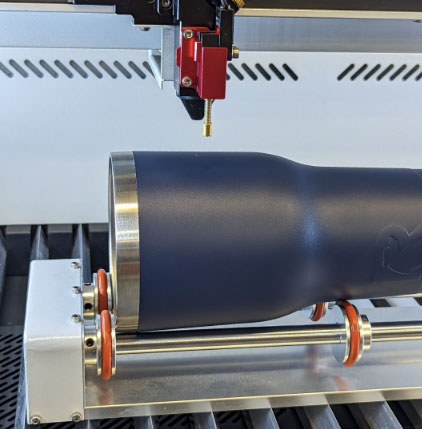
- Jog the laser head out of the way and then place the workpiece back onto the rotary. Rotate the workpiece so that the center of the area you wish to engrave is facing upwards.
NOTE: The way you position the laser head, “Origin”, and area of the workpiece you wish to engrave will vary depending on the “Job Origin” selection button selected in Lightburn. These instructions assume the Center control button is being used.
- Gently push/pull the gantry until the red dot is over the highest point of the workpiece.
- Use the “LEFT/RIGHT” arrow keys on the keypad to jog the laser head over the area of the workpiece you wish to engrave.
- Press the “Z/U” button on the keypad so that “Z Move” is highlighted. Use the keypad to move the bed up so it is just a few mm from the laser head.
- Manually focus the laser using the supplied 20.5 mm Focus Gauge. Press the RIGHT arrow key to incrementally lower the table until the “step” for the desired focal distance fits snugly between the workpiece and the nozzle. If you are unfamiliar with how to manually focus, see our article about manually focusing.
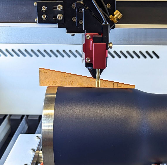
NOTE: A focus of 8.5 mm is recommended for most items, however a couple mm out of focus (ex. 10.5 mm) will yield better results with heat sensitive items like glass or metal cups with thick coatings, as this will prevent flash back and potential tube damage when engraving with such materials.
CAUTION: Never try to raise the table with a focus gauge beneath the nozzle, as a collision between the laser head and gauge could cause damage. The table should always be LOWERED into the focus, not raised. Raising the table too high with the rotary plugged in can result in a collision that can damage the “Rotary Port” & “Rotary Plug”.
.
- Use the “LEFT/RIGHT” arrow keys to move the red pointer to the position on the workpiece, where you’d like for the center of your artwork to be.
- Press “ORIGIN” on the keypad to set the starting position.
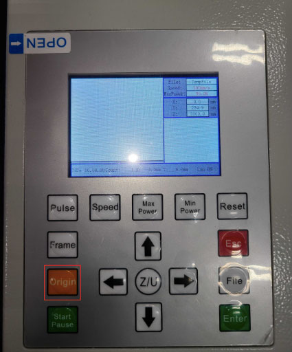
NOTE: The Origin/Starting Position corresponds to where the “Job Origin” (little green square) is positioned in Lightburn. The center control button was used in this example and is usually best when using the Smart Rotary.
- Press “FRAME” on the keypad to ensure the perimeter of the job is in agreement with the desired engraving location on the workpiece. If it's not, adjust the “ORIGIN” per the previous step until the desired location is achieved.
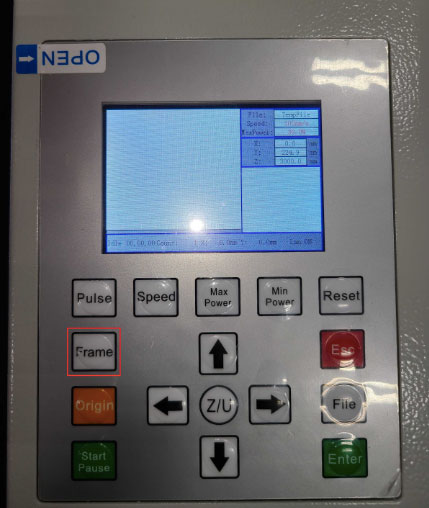
NOTE: Watch both rollers and the workpiece closely as the laser head frames to ensure smooth transmission in any direction. If the workpiece wobbles, slips, or binds at any point, reevaluate the way it’s positioned on the rollers or the positioning of the wheels. It may be necessary to remove the cup and readjust.
Y Slop Error
- If you receive a Y Slop Error on the keypad, press “ESC” to exit the error screen. Then, press “ESC” again, so that the laser returns to the Origin point.
- Use the UP/DOWN arrow keys to jog the rollers back to the center of the Y-axis.
NOTE: The Y-coordinate on the keypad should read the following (+/- 5 mm):
- 150 mm for MIRA 5
- 225 mm for MIRA 7
- 300 mm for MIRA 9
- Press ORIGIN to record the new starting position. Return to the previous step and attempt to Frame again.
- Adjust the Y coordinate value up/down as needed until the design frames. Ensure “ORIGIN” is being pressed on the keypad after each adjustment made.
Pre-Launch Checklist
- The proper “Rotary Settings” have been loaded onto the machine.
- The cup is set up with the proper “Rotary Settings”.
- The Smart Rotary is plugged into the machine’s “Rotary Port”.
- The rotary cord is clear from the rollers, gantry, and laser head.
- The Smart Rotary is aligned with the gantry.
- The red dot is over the highest point of the workpiece.
- The file was sent and transferred to the machine properly. The user should see the name of the file on the top right of the keypad display
- The laser is focused to the correct specifications for the workplace.
- The design’s origin in the desired location.
- The design frames in the desired location.
- The workpiece is level on the rotary, and any bumps, ridges, or raised logos are not in the direct path of the wheels.
- The workpiece rotates smoothly with the rollers without losing traction.
Launch
WARNING: In the event of a fire or a collision, Pause the job or press the Emergency Stop button and contact Customer Support.
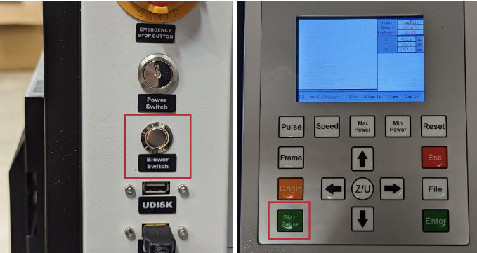
- Ready!? Gently close the lid, turn ON the exhaust system, and put on your laser safety glasses. Press “START/PAUSE” on the keypad and keep your finger resting on the button, in case you feel the need to Pause the operation.
- When the job is complete, push the gantry out of the way by hand. You can then remove the workpiece from the Smart Rotary.
- Carefully clean the piece once removed.
NOTE: Avoid moving the Smart Rotary if you wish to run another job on the same type of item. If running the same file again, simply load the new workpiece onto the Smart Rotary. Ensure the laser focus is still correct and the rotary is still squared, then press Start. You will not need to reposition the laser head or the rollers. The previously set Origin will maintain the starting position until you decide to change it. It is good practice to frame the job again to verify the job positioning is to your liking before running.
Returning to Flat Engraving Settings
When you are done using the Smart Rotary, you MUST return your laser settings back to flat settings and remove the Smart Rotary from the machine bed.
WARNING: It is imperative that the flat settings are flashed to the controller and the rotary is removed before powering down the machine. Failure to do so can result in damage to the machine.
- Plug the USB thumb drive that came with your laser into an open USB port on your computer.
- Connect your computer with Lightburn installed to the machine via your preferred method of connection. For this guide, a USB connection was used.
- In Lightburn:
- Click on “Edit” along the top toolbar.
- Click on “Machine Settings”.
- In the “Machine Settings” window:
- Click “Load from File” on the bottom left portion of the window.
- Navigate to the machine USB in your file explorer.
- Open the “Settings” folder.
- Open the “Rotary Settings” folder and select “Flat Settings.lbset” file.
- With the “Flat Settings” file selected click “Open”.
- Click “Write” to overwrite the settings to the controller.
After the settings are written, there should be a small message near the buttons at the bottom of the “Machine Settings” window that says “Controller settings written successfully”. If there is a message saying “Communication with controller failed”, click “Read” towards the bottom right of the window, return to Step 4.1, and repeat the process.
- Click “Read” after the settings are successfully flashed. Scroll down in the window to the “Rotary Parameters” section.
- Verify that “Enable Rotary” is set to “False”.
- Click “OK” on the “Machine Settings” window to close.
- Click “Load from File” on the bottom left portion of the window.
CAUTION: If the “Enable Rotary” setting is NOT set to “False”, that means the settings were not loaded properly. Return to Step 4.1 and repeat the process.
NOTE: Never turn off the laser prior to returning to “Flat Settings”. Doing so will make it impossible for the laser to initialize correctly upon start up, which will result in an extremely slow initialization sequence and a limited range of motion along the Y-axis. If this happens, simply press “ESC” on the keypad during the initialization sequence and follow the previous steps.
Tear Down
Once “Flat Settings” have been flashed to the controller, there are just a few more steps to return the machine to its normal configuration.
- Unplug the Smart Rotary from the “Rotary Port”.
- Remove the rotary from the machine bed, as well as any other material that is in there.
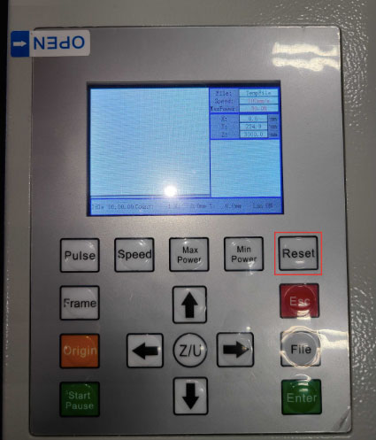
- Press “RESET” on the machine keypad. Allow the machine to fully reset.
CAUTION: Always ensure that the laser head is not on a collision course with your workpiece or the Smart Rotary prior to pressing “RESET”. Not doing so can result in a collision, which may damage the machine or knock the laser head and Mirror 3 out of alignment.
That's it!
If you have any questions or concerns, please send us an email at support@aeonlaser.us for the fastest service. If your laser is malfunctioning, please submit a support ticket.
Happy Lasering!


