-

Getting Started 16
-

Maintenance 14
-

Troubleshooting 14
-

Repair 8
-

Laser 101 3
-

Materials 10
-

Accessories 20
-

Multi-Roller 7
-

LightBurn 9
Optimizing Tumbler Settings


What you will learn
In this guide, you will learn the basics of the tests needed to optimize your machine's settings when engraving a tumbler or similar cylindrical object.
When to do this
The aim of this document is to provide a foundation from which to adjust and refine your settings, specifically when working with a tumbler. This document should be resourced when initially setting up your machine for tumbler projects, before starting a production run to ensure the settings are still best for the specific material and design requirements, or when switching between different tumbler brands or coatings.
What you will need
- Tumblers to test
- Focus Gauge
- Notebook
Need assistance?
Book time with a qualified technician and learn how to dial in the ideal settings for flawless tumbler engravings.
Preface
The testing procedure covered in this guide is geared towards performing a full wrap on an item, but this procedure works equally as well for any sized design. Ideally, we want to shoot for the shortest cycle time that also provides a "passable” finished product. If it looks bad, obviously we can't use it.
This guide will cover the process that was used here at the shop to identify the best settings to use when performing a full wrap on a tumbler. It is written following the steps and methods used to discover the optimal settings, following the Scientific Method.
The following testing procedures and conclusions are purely representative and serve as an example for how the user can effectively optimize their tumbler engraving settings. It is more than likely that your specific tumbler will have different dimensions, a different coating, etc. and thus may yield different results.
NOTE: For general information on finding settings, see our AEON Laser Knowledge Base article on understanding materials and settings. See our AEON Laser Knowledge Base article(s) for information on how to set up and use a rotary.
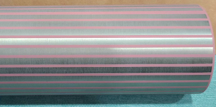
Speed Testing
The purpose of this test is to find an engraving speed that balances efficiency and quality. Start with a long, skinny rectangle to find the most efficient scan speed across the entire height of the cup. Essentially, we are looking for minimal overscan over a simulated full area pass over the cup. For a smaller design, size the speed test rectangles to be the length of the design.
General Settings
- Machine: MIRA7 60W
- Power: 100% - Power is maxed because high speeds are being tested.
- LPI (Lines Per Inch): 400 - This LPI setting is the rough median for most materials. Changing LPI will have SIGNIFICANT changes on both output and job time.
- Lens:2.5" (63.5 mm) - This lens is different from the standard lens that comes with a MIRA. The deeper focal depth was used to provide a wider available focal range.
- File Shape/Size for Test: 180 mm wide x 5 mm tall - The engravable area on the cup used was 180 mm from the mouth of the cup to the bottom.
Procedure
- Speed Range Tested:
- 300 mm/s to 1200 mm/s for efficiency across nearly the full range of speeds the machine is capable of producing.
- 350 mm/s to 1150 mm/s in 100 mm/s increments for more precise data.
- Results:
- All times +/- 0.5 seconds.
Speed (mm/s) Run Time (seconds) 300 48.73 400 38.51 500 32.02 600 28.30 700 25.26 800 23.06 900 21.68 1000 20.42 1100 19.37 1200 18.83 350 44.14 450 35.19 550 30.06 650 26.60 750 24.30 850 22.16 950 21.06 1050 19.91 1150 19.03
- All times +/- 0.5 seconds.
Conclusion
A wide deviation in times was seen across the range tested, as expected. Speeds from 700 to 1000 mm/s showed minimal time differences (~5 seconds variance) and yielded a good quality result.
The low range of speeds (300 mm/s to 450 mm/s) led to the coating burning onto the cup instead of ablating properly. This was a result of the power used, in conjunction with the low speeds. The higher range of speeds (1000 mm/s to 1200 mm/s) looked good from a distance and were notably faster, but the edges of the engrave yielded a poor result.
Since the goal here is to find a speed that is both fast and yields a usable result, a speed of 950 mm/s was identified as optimal.
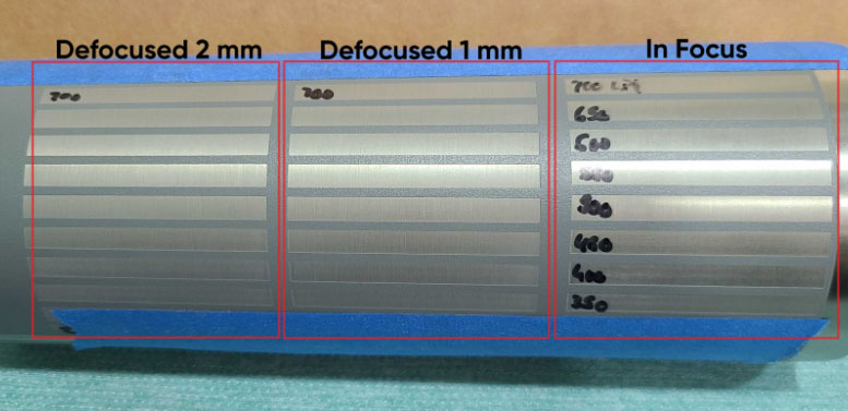
Focal Depth Testing
The purpose of this test is to determine the usable focal depth(s) for quality engraving with a 2.5" lens. Most focal lenses have a 1 to 2 mm range both above and below the best focal point, known as the defocused range, in which the machine will still engrave effectively with a larger dot size.
Calibrating the focus to use a larger dot size helps smooth the edges of the design, as well as cut down on overall job time due to a larger area being subjected to the laser beam.
Lens Specifications
- Diameter: 18 mm
- Focal Depth: 2.5” (63.5 mm)
See details on the 2.5" lens used.
Procedure
Focal Depth Configuration
- Manual Focal Gauge used to focus, as the standard machine configuration for auto focus is for a 2” (50.8 mm) lens.
- Auto focus on the manual gauge is approximately 8.5 mm. Adding ½” (12.7 mm) to this yields a manual focal depth of about 21 mm.
Quality Focal Range
Generally, lenses have a 1 to 2 mm range above and below the focal point that the machine will still engrave effectively at. With this lens configuration, that is a range of 19 mm to 23 mm with the manual focal gauge.
NOTE: The first generation of manual focal gauges maxes out at 20.5 mm. To focus to a deeper depth, reference the Z depth on the keypad to calculate the distance needed to travel.
A basic focal ramp test can be performed to fine tune the ideal focal range. Simply move the bed up/down 1mm at a time after setting the depth to the calculated ideal focal point (21 mm on the manual gauge in this example). Pulse into some scrap material at each depth and look for the finest pulse marks made, thus finding the effective work area and defocused work range. Beyond this range, significant quality loss occurs due to excessive diversion of the beam.
Conclusion
Roughly a 5mm range was found to produce an effective result. It is important to know what range is effective for tumblers with a taper (like a Stanley cup). Due to the geometry of the cup, it will be impossible to have the entire surface perfectly level and in focus. Finding the effective range will enable you to accurately position the cup on the rotary so the surface will be within the effective range across the entire area of the tumbler.
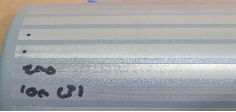
LPI Settings Testing
The purpose of this test is to identify the ideal LPI setting. We are looking for a balance of speed and thorough coating removal without compromising the finish. Low LPI will lead to a quicker job cycle time, but too low of an LPI will not fully remove the coating from the cup and thus yield an unusable result.
It is important to acknowledge that the results of this portion will be based on your personal preference. While cycle time is important, LPI is a large factor in determining finish. If you are looking for a matte finish as opposed to a gloss finish, and higher LPI gives you that result, use the higher LPI. Ultimately, this section is to determine how you want the finished product to look.
General Settings
- Speed: 950 mm/s - This is the speed setting found to be optimal during speed testing.
- Power: 100% - Power is maxed because of the high speed being used.
- Lens: 2.5" (63.5 mm) - Focused to the depth found in the focal depth testing.
- File Shape/Size for Test: 50 mm wide x 5 mm tall - The area has been reduced to more closely resemble actual engraving area sizes on the file and reduce test time.
Procedure
- LPI Range Tested:
- From 100 LPI to 1000 LPI for efficiency and finish results across a wide range of LPI values the machine is capable of producing.
- 350 LPI to 750 LPI in 100 LPI increments for more precise data across a common range of LPI seen in the field.
- Results:
- All finish results are based on visual inspection and opinion.
- All times +/- 0.5 seconds.
- All results tested over the full range of focus found in the previous section.
| LPI Value | Time (seconds) | Finish Result |
| 100 | 2.40 | Coating not fully removed from the tumbler |
| 200 | 4.58 | Coating not fully removed from the tumbler |
| 300 | 5.23 | Coating nearly fully removed from the tumbler. Some spots still clearly visible, especially where further out of focus. |
| 400 | 8.16 | Coating fully removed, standard gloss finish. |
| 500 | 9.24 | Coating fully removed, standard gloss finish. |
| 600 | 11.47 | Coating fully removed, standard/low gloss finish. |
| 700 | 13.60 | Coating fully removed, low gloss finish. |
| 800 | 14.33 | Coating fully removed, low gloss/matte finish. |
| 900 | 17.38 | Coating fully removed, low gloss/matte finish. Possible overburning. |
| 1000 | 18.83 | Coating fully removed, lower gloss/matte finish. Possible overburning. |
| 350 | 5.91 | Coating nearly fully removed from the tumbler. Some spots still visible, especially where further out of focus. |
| 450 | 8.88 | Coating fully removed, standard gloss finish. |
| 550 | 10.05 | Coating fully removed, standard gloss finish. |
| 650 | 12.27 | Coating fully removed, standard/low gloss finish. |
| 750 | 14.02 | Coating fully removed, low gloss/matte finish. |
Conclusion
The results from this test gave an effective range of LPI values with various finishes. Based on the visual results, time results, and using our best judgment, an effective LPI range would be from about 400 LPI to 800 LPI (depending on the desired finish). A standard gloss finish is what is most commonly used, so with that in mind, and taking job cycle time into mind as well, the LPI value that will be used for the job is 400 LPI.
Full Wrap Testing
The purpose of this test is to assess the engraving quality of designs that wrap fully around a tapered tumbler, ensuring it stays uniform and precise across the entire surface shape. This is important for maintaining aesthetic appeal and functional consistency for engraved designs where the surface curvature and tapers can affect the engraving process.
General Settings
- Speed: 950 mm/s - This is the speed setting found to be optimal during speed testing.
- Power: 100% - Power is maxed because of the high speed being used.
- LPI (Lines Per Inch): 400 - Found to deliver a good balance between job resolution and efficiency.
- Lens: 2.5" (63.5 mm) - Focused to the depth found in the focal depth testing.
- Rotary Setup: PiBurn Grip
- Due to the high speeds used a chuck style rotary was optimal, as it holds the cup most securely.
- Braces/magnets were used to help hold the rotary in place to compensate for the inherent vibrations that come with high speeds.
Procedure
The test involved engraving a design that wrapped entirely about a tapered tumbler to evaluate the consistency and quality of engraves across different contours and depths in tumbler design. To ensure the design wraps the cup fully, the file dimensions were set to match the circumference of the tumbler.
- Results:
- The full-wrap design showed solid results. This would be an easily passable product. Overall, the settings found allowed for a uniform appearance over the entire tumbler surface.
- Total job time was 19 minutes and 40 seconds.
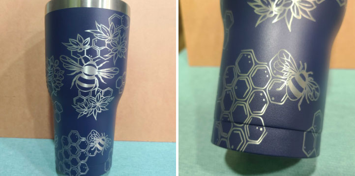
Conclusion
The settings used yielded a passable quality of engrave. Design consistency and clarity of the details were maintained throughout the surface, indicating a success in the settings testing process.
Closing Remarks
Ultimately, this guide should serve as a resource for achieving optimal precision and quality in cylindrical object engraving. Through our tests surrounding speed, LPI, and focal depth, your file settings can be tailored to meet the unique challenges presented by varying tumbler designs- whether for full wraps or within specific focal ranges. Breaking down these parameters and tackling them individually will enhance the aesthetic and functional aspects of your engravings and improve efficiency when operating in the future.
With ever-expanding technologies and materials selection, the principles laid out in this guide should serve as a foundational resource for users seeking to ensure their product stays on the ball with artistic standards and maintaining commercial presence. Continuing to experiment and explore with your machine is encouraged, and we hope this guide helps you to refine your techniques and push the boundaries of what your machine is capable of!
If you have any questions or concerns, please send us an email at support@aeonlaser.us for the fastest service. If your laser is malfunctioning, please submit a support ticket.
Did you find this document helpful? Let us know what you liked or what we can improve on by sending an email to helpusgrow@aeonlaser.us.
Happy Lasering!


