-

Getting Started 16
-

Maintenance 14
-

Troubleshooting 14
-

Repair 8
-

Laser 101 3
-

Materials 10
-

Accessories 20
-

Multi-Roller 7
-

LightBurn 9
5 Point Test - MIRA


Overview
What you will learn
In this guide, you will learn how to perform a 5 point test on a MIRA.
When to do this
A 5 point test is a good troubleshooting tactic when trying to identify why the machine may not be cutting or engraving, as well as a final verification step after checking the full alignment of the machine.
What you need
- Painter's Tape
- 2.5 mm Allen Key
Video
Steps
- Power the machine ON and allow it to fully reset.
- Jog the laser head to the center of the bed (+/- 5 mm).
Coordinates for bed center:- MIRA5: X = 250 mm Y = 150 mm
- MIRA7: X = 350 mm Y = 225 mm
- MIRA9: X = 450 mm Y = 300 mm
- Take a 1” to 2” piece of painter's tape and press firmly into the nozzle. The goal in pressing the tape into the nozzle is to form a divot, which will show where the beam is hitting in reference to the edges of the hole in the nozzle.
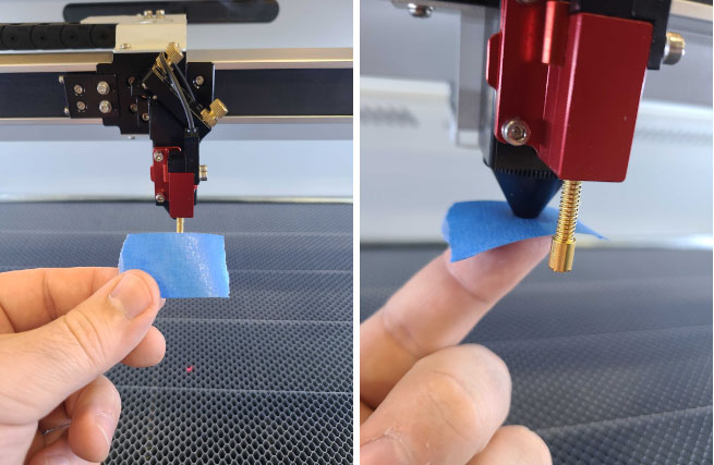
- Close the lid and quickly press “PULSE” on the keypad.
- Open the lid and gently remove the tape from the nozzle. Be careful not to touch the divot or pulse spot on the tape.
NOTE: Do not fold or rotate the tape when removing. The direction the tape was stuck on matters, as the location of the pulse mark will be used as reference to make the necessary adjustments.
To help maintain a constant direction orientation, a little arrow or something similar can be drawn on the tape for reference.
- Inspect the pulse mark. Look for the shape of the pulse, as well as where the mark is located in relation to the center of the divot.
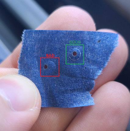
- Adjust the alignment as needed (process detailed below) to get the pulse mark as close to the center of the divot as possible.
NOTE: After adjusting, ALWAYS pulse into a fresh spot on the tape after to check where the pulse mark has moved to.
- Once the pulse has been aligned to the center of the divot in the center of the bed, grab a fresh piece of tape and apply it to the nozzle as done in Step 3.
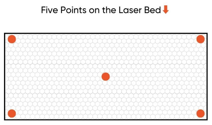
- Pulse the machine in 5 points, moving the tape in tandem to correlate to where the machine is being pulsed.
- The 5 points to pulse are the center of the bed, back left corner, back right corner, front left corner, and front right corner.
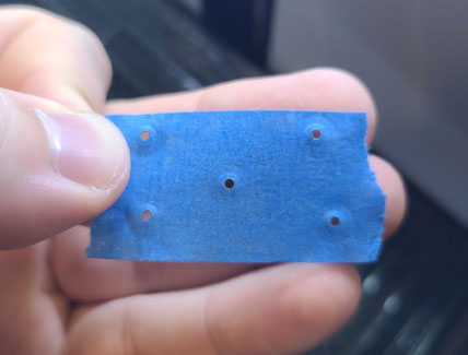
- Inspect the results of the full 5 point test. Do all of the pulses look like they are hitting in the same spot across the bed? If so, the 5 point test is complete!
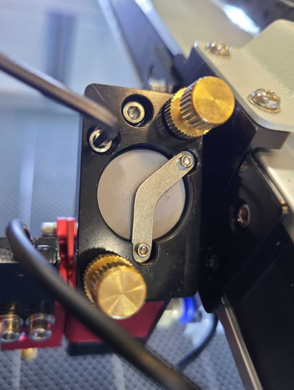
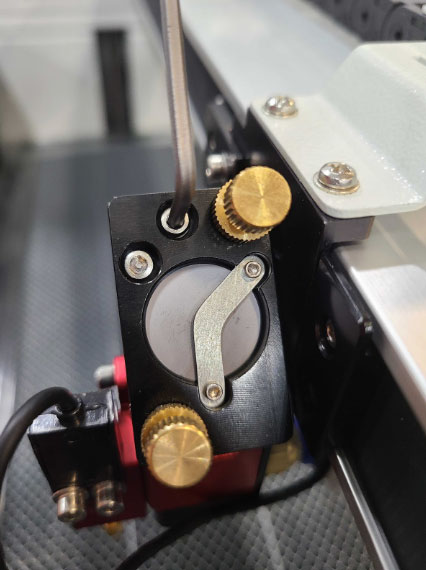
How to Adjust the 5 Point
The alignment knobs on the Mirror 3 bracket serve a dual purpose, facilitating adjustments for both the general alignment of Mirror 3 and the precise positioning of pulse marks during a 5-point test. It's worth noting that, unlike the Mirror 3 alignment procedure where the lens housing is removed from the laser head, adjustments for pulse marks require heightened precision due to the lens being in place during the fine-tuning process.
NOTE: All adjustments should be made in reference to the center pulse point. Only perform the full 5 point test if the center pulse mark is acceptable.
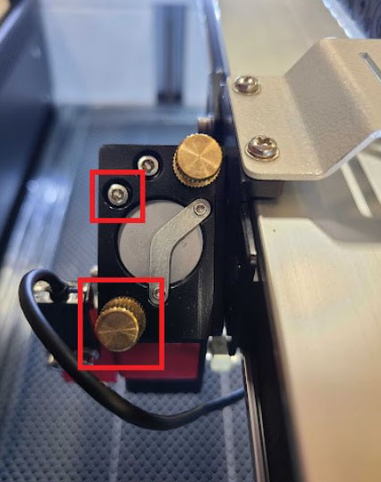
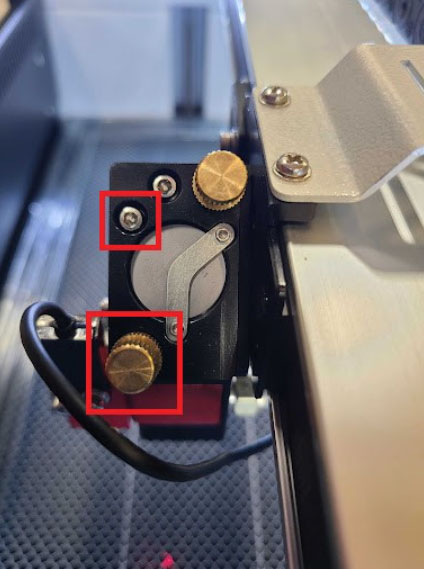
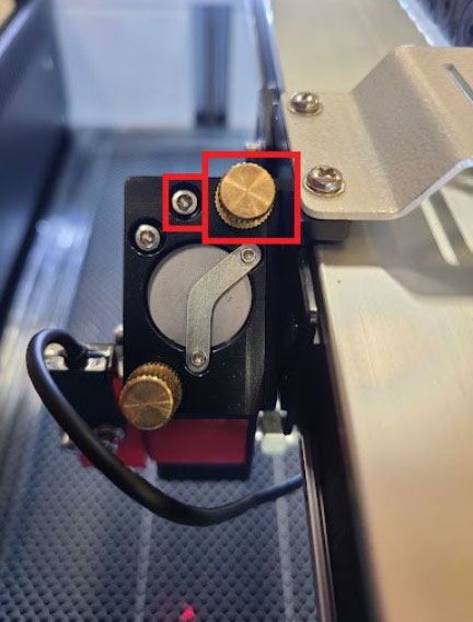
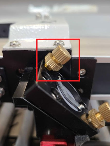
Leftward Adjustment
The circled brass alignment knob and set screw will be used for leftward movement of the pulse mark. Move the auto focus sensor wire out of the way as needed.
- Slightly loosen the set screw with a 2.5 mm Allen key.
- Loosen the lock nut on the brass alignment knob.
- Slightly loosen the alignment knob (turn counter clockwise).
- Tighten the lock nut.
- Tighten the set screw.
CAUTION: Do not overtorque the set screw. The threading in the laser head is easy to strip. Stripping the threading will leave the machine unable to be aligned and will need the laser head main chassis to be replaced. The screw should be firm and the mirror bracket should not wiggle.
- Get a fresh piece of tape and put it on the nozzle as instructed in the previous section.
- Pulse in the center of the bed.
- Remove the tape and inspect the location of the pulse mark.
- Repeat the process as needed until the pulse mark is centered in the divot.
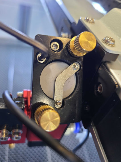
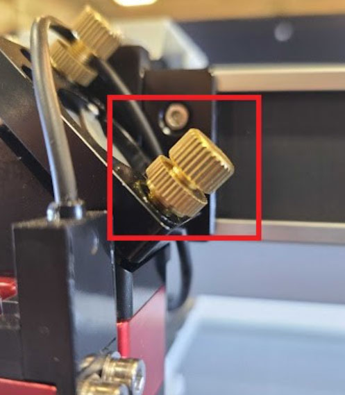
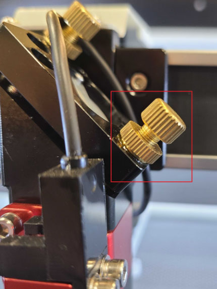
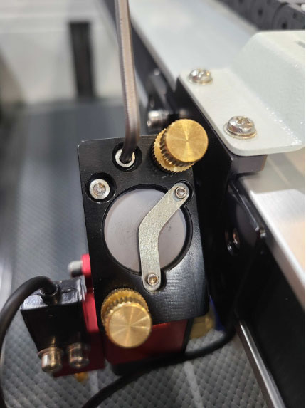
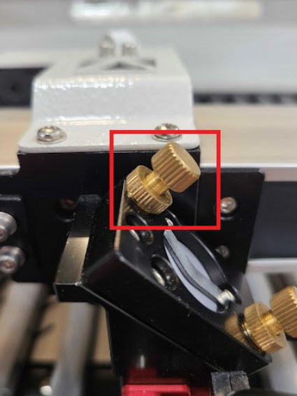
Rightward Adjustment
The circled brass alignment knob and set screw will be used for rightward movement of the pulse mark. Move the auto focus sensor wire out of the way as needed.
- Slightly loosen the set screw with a 2.5 mm Allen key.
- Loosen the lock nut on the brass alignment knob.
- Slightly tighten the alignment knob (turn clockwise).
- Tighten the lock nut.
- Tighten the set screw.
CAUTION: Do not overtorque the set screw. The threading in the laser head is easy to strip. Stripping the threading will leave the machine unable to be aligned and will need the laser head main chassis to be replaced. The screw should be firm and the mirror bracket should not wiggle.
- Get a fresh piece of tape and put it on the nozzle as instructed in the previous section.
- Pulse in the center of the bed.
- Remove the tape and inspect the location of the pulse mark.
- Repeat the process as needed until the pulse mark is centered in the divot.
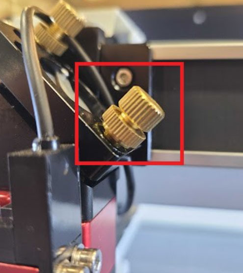
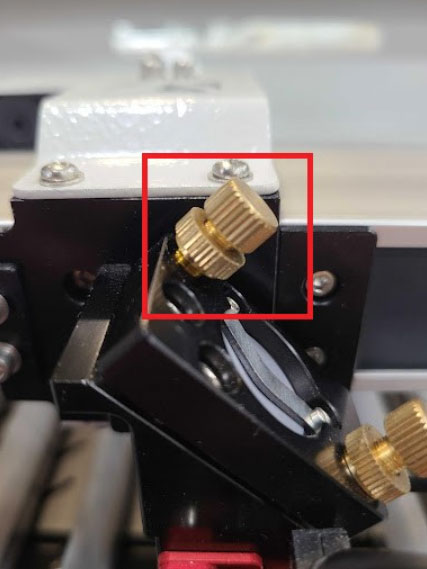
Downward Adjustment
The circled brass alignment knob and set screw will be used for downward movement of the pulse mark. Move the auto focus sensor wire out of the way as needed.
- Slightly loosen the set screw with a 2.5 mm Allen key.
- Loosen the lock nut on the brass alignment knob.
- Slightly loosen the alignment knob (turn counter clockwise).
- Tighten the lock nut.

- Tighten the set screw.
CAUTION: Do not overtorque the set screw. The threading in the laser head is easy to strip. Stripping the threading will leave the machine unable to be aligned and will need the laser head main chassis to be replaced. The screw should be firm and the mirror bracket should not wiggle.
- Get a fresh piece of tape and put it on the nozzle as instructed in the previous section.
- Pulse in the center of the bed.
- Remove the tape and inspect the location of the pulse mark.
- Repeat the process as needed until the pulse mark is centered in the divot.
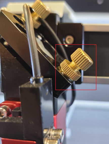
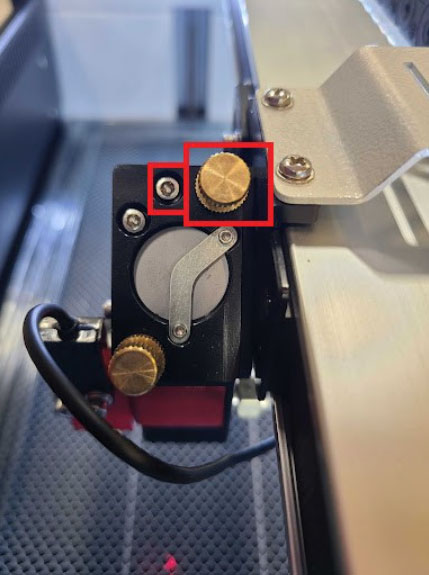
Upward Adjustment
The circled brass alignment knob and set screw will be used for upward movement of the pulse mark. Move the auto focus sensor wire out of the way as needed.
- Loosen the set screw with a 2.5 mm Allen key.
- Loosen the lock nut on the brass alignment knob.
- Slightly tighten the alignment knob (turn clockwise).
- Tighten the lock nut.
- Tighten the set screw.
CAUTION: Do not overtorque the set screw. The threading in the laser head is easy to strip. Stripping the threading will leave the machine unable to be aligned and will need the laser head main chassis to be replaced. The screw should be firm and the mirror bracket should not wiggle.
- Get a fresh piece of tape and put it on the nozzle as instructed in the previous section.
- Pulse in the center of the bed.
- Remove the tape and inspect the location of the pulse mark.
- Repeat the process as needed until the pulse mark is centered in the divot.
If you have any questions or concerns, please send us an email at support@aeonlaser.us for the fastest service. If your laser is malfunctioning, please submit a support ticket.
Did you find this document helpful? Let us know what you liked or what we can improve on by sending an email to helpusgrow@aeonlaser.us.
Happy Lasering!


