-

Getting Started 16
-

Maintenance 14
-

Troubleshooting 14
-

Repair 8
-

Laser 101 3
-

Materials 10
-

Accessories 20
-

Multi-Roller 7
-

LightBurn 9
Material Rapid Test


Overview
What you will learn
In this guide, you will learn how to understand and use the Material Rapid Test file.
When to do this
The Material Rapid Test file can be used to help when trying to identify the proper settings for a material you wish to engrave and cut. Whether you're a seasoned pro or just starting out, this file is designed to help you pinpoint the perfect settings for engraving and cutting materials with your laser machine.
What you need
- Test/Scrap Material
- Computer with LightBurn
Need assistance?
Book time with a qualified technician and master the material rapid test process to identify ideal laser settings.
NOTE: If you have never run a job on your machine before, see our video on MIRA First Time Engraving or NOVA First Time Engraving. If you are unfamiliar with LightBurn and some of its basic features, see our AEON Laser Knowledge Base article on LightBurn Basics. LightBurn has a ton of great resources on their website as well.
What is the Material Rapid Test?
The Material Rapid Test (MRT) is an engraving and cutting test file designed to help identify what settings to use with your laser. The test showcases several different settings, and how they will look on/affect the material you chose to engrave. By running this test, you can explore a range of settings and observe how they impact the material you're working with. Plus, the file can be customized to tailor the testing parameters to your specific needs.
Making the File Work for You
If you don't like the speed, power, or any other settings on the MRT file or just want to change them to experiment, feel free to edit the layer settings as needed. The goal of this file is to act as a gauge to help find settings and their outcomes. If you only need to run a test cut, you can use the “Cut Selected Graphics” feature in LightBurn to only run the cut section of the test. The same is true for any portion of the file.
You don't have to run full sections as well. Want to see how the 15% to 30% pie slices engrave? Only select and run them. Experimenting with this file on some scrap material will not only help in identifying settings, but also help with generic LightBurn use as well.
If you are unfamiliar with some of the more basic features in LightBurn, see the LightBurn website or our AEON Laser Knowledge Base article on LightBurn Basics.
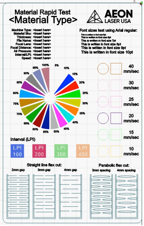
The MRT Dissected
Information and Font Section
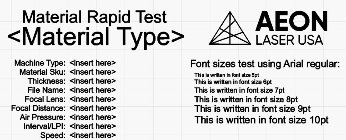
This section provides key information about the material, machine type, and other settings. Feel free to customize this section to match your setup, or leave it as is. It is left generic by design, as the file can be used on a wide array of machines and materials. All of the text (aside from the AEON logo) can be double clicked to edit.
- Material Type - This line can be edited to reflect the material type the MRT will be run on. Wood, acrylic, etc.
- Machine Type - This line can be edited to reflect the machine used to run the file. MIRA7, NOVA14, etc.
- Material SKU - This line can be edited to reflect the SKU of the material type, if applicable.
- Thickness - This line can be edited to reflect the thickness of the material the MRT will be run on.
- File Name - This line can be edited to reflect the name of the production file you are identifying settings for.
- Focal Lens - This line can be edited to reflect the lens size that is installed to run the MRT with.
- Focal Distance - This line can be edited to reflect the focal distance used to run the file.
- Air Pressure - This line can be edited to reflect the air pressure used when running the MRT file. This is geared for recording the value of an external air compressor. The internal air leaves the nozzle at approximately 2-3 PSI.
- Interval/LPI - This line can be edited to reflect the LPI used for a majority of the engraving layers. The generic LPI is set to 300, but this can be customized as needed.
- Speed - This line can be edited to reflect the engraving speed used for a majority of the engraving layers. The generic speed setting is 300 mm/s, but this can be customized as needed.
- Font Section - The right portion shows different sized fonts and how they will engrave. The font can be changed to match the font you will use; the generic font style is Arial.
Cut Test Section
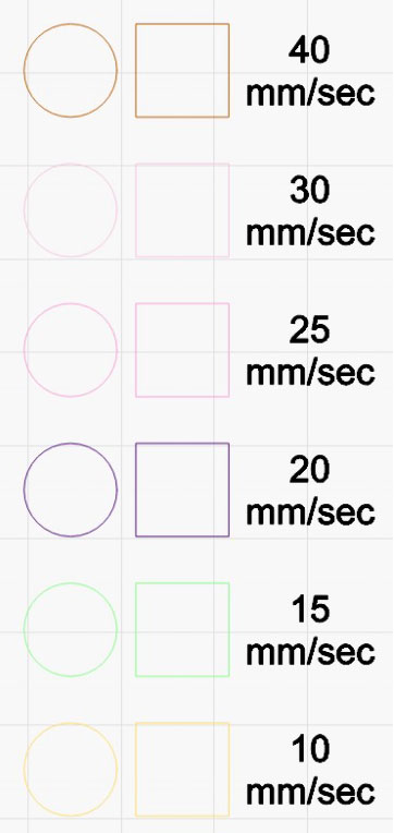
The center right side of the file contains the cut test section. The generic layer settings display a common range of cut speeds for material at a power setting of 90%. Each speed correlates to the small circle and square to its left. The air pressure used while cutting will make a significant difference as well, so keep what air pressure was used in mind when looking at the results of this test.
The idea behind this section is to see if and how the material you are trying to cut will cut. There are a few important points to look at when running this portion of the MRT file.
- Did it cut? First and foremost, what portions of the section actually cut through? Depending on material type and tube wattage, there are a variety of outcomes that can come from this test. Use your judgment here as to what speeds will or will not cut.
- How does the edge look? Examine the cutout pieces after the job has finished. Pay close attention to the edge and how it looks. The acrylic you tried to cut may have come out at 40 mm/s, but the edge looks glossy and much more smooth at 20 mm/s. Use your judgment to determine which edge type you like the best.
- Any flare ups? When the file was cutting, did you notice any fires or excessive burning in the area? That likely means either the power is too high, or the speed is too slow. Use your judgment to determine a balance of power and speed when cutting.
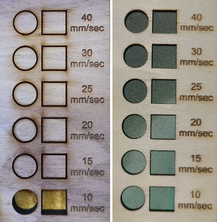
Example
In the images below we can see how a 60W CO2 tube cuts ¼” MDF and ⅛” Birch plywood. The only setting that was able to cut the MDF was 10 mm/s with an external air compressor providing 20 PSI of air. In contrast, the same machine with the same settings was able to cut the Birch with every speed setting. This does not mean there is anything wrong with the file or the machine, it simply shows us that a 60W CO2 tube MUST be cutting at speeds of 10 mm/s or slower to be able to cut this ¼” MDF material. From here we can fine tune a cut setting that gives the cleanest edge with the most efficient job time.
It is important to note that the settings in the file are generic. All of the layers in the MRT can be edited if you choose to do so. If you get a burnt edge even at the fastest cut speed, edit the layer settings to try an even faster speed range, or a lower power range to compensate.
Engraving Test Section
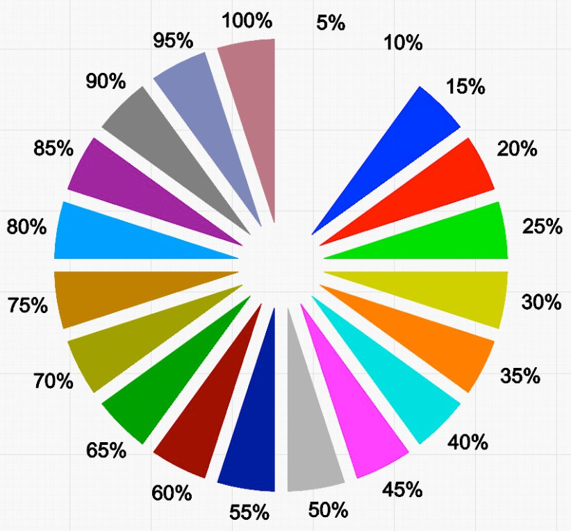
The center left side of the file contains the engraving test section. The generic speed setting for the section is 300 mm/s, with a full range of power in 5% intervals. Each power percentage correlates to the nearest pie slice. Generally a lower air PSI leads to better results when engraving, so this section should be run with the air assist setting in LightBurn toggled OFF, but feel free to try with air assist ON and see how it looks. Toggling air assist OFF will enable the machine to engrave using only its internal air pump at around 2-3 PSI.
NOTE: There are no slices for 5% and 10%, as most tubes will not mark at a power setting that low.
The idea behind this section is to see if and how the material you are trying to engrave will engrave. There are a few points to look at when running this portion of the MRT file.
- Engraving depth - Are you looking for a deep and dark engrave, or something just kissing the surface of the material? Use the individual slices to see how different powers will affect the material.
- Engraving speed - The speed of this whole section is set to 300 mm/s, but it does not have to stay that way. If you are wanting to try faster speeds, simply edit the speed setting for each slice in the “Cuts/Layers” window within LightBurn.
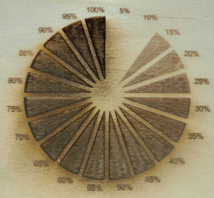
Example
In the image below we can see how the machine engraved across its full power range on ⅛” Birch plywood. This gives us a visual representation of what each power setting will look like at 300 mm/s. We can then identify which slice looks best for the intended application. If we wanted a deeper engrave, the higher power values would be needed. For a surface level light engrave, lower power gives a better result. The depth and darkness of the engrave is entirely personal preference for what you want the end result to look like. Use your best judgment, and try running the test with different speeds or LPI values to see how that changes the result.
NOTE: The settings in the file are generic. All of the layers in the MRT can be edited if you choose to do so. If you do not like the results you get, edit the layer settings to try a different speed. The file will show the full power range, so no need to edit any power values.
Interval (LPI) Test Section
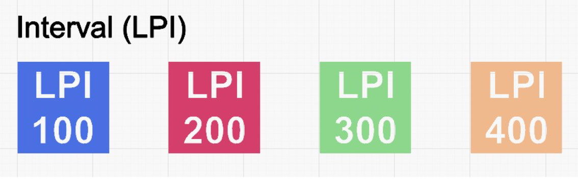
Just under the engraving test section is the LPI test section.
Lines per inch, or LPI, is how many lines the machine will engrave over a 1” area. “Line Interval” is essentially the same, except it refers to the spacing between each line instead of how many lines are in a 1” space. LPI and Line Interval will have an inverse relationship. As LPI increases, the Line Interval will decrease, as there is less space between the lines that are being engraved. The LPI determines the resolution and level of detail in the engraved design. Higher LPI will give a smoother engraving result, at the cost of an increase in job time due to the laser taking smaller jumps between lines when engraving. Higer LPI will also put more total energy on the area that is being engraved, so the engraving will be deeper and darker as LPI increases.
Most jobs will look best with an LPI of 300-500, though there are use cases for both higher and lower values. The idea behind this section is similar to the engraving test section. Look at each box after the job has finished to see how the material you are trying to engrave will engrave.
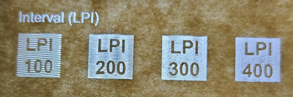
Example
In the image below we can see how the LPI range looks on acrylic. Both boxes below 300 LPI have easily visible gaps between the lines in the engrave. The desired result is a smooth engrave, so we will want to use an LPI of 300 or above, and fine tune our results from there.
NOTE: The settings in the file are generic. All of the layers in the MRT can be edited if you choose to do so. If you do not like the results you get, edit the layer settings to try different LPI values.
Flex Cut Section
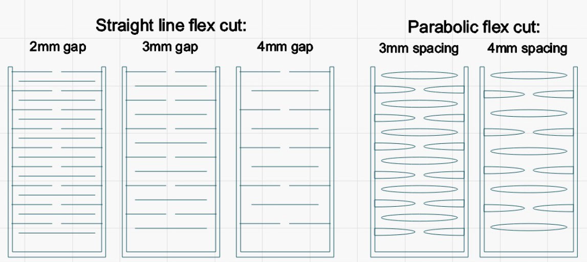
The bottom of the file contains the flex cut section. These cuts are on the same layer as the final outline cut for the full material test as well. This section simply showcases the flex cutting capabilities of the machine. These cuts work best on wood, and will allow for a minor bend in the material.
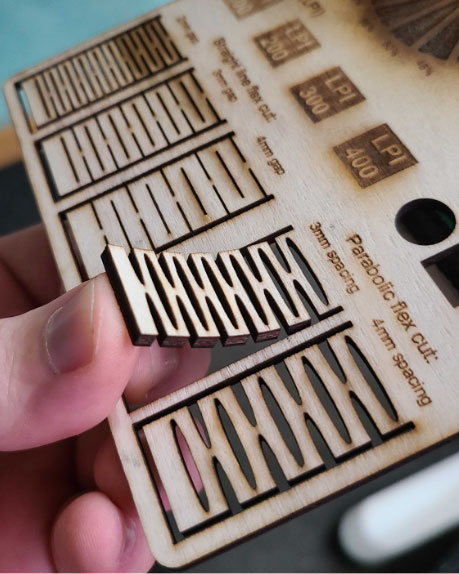
NOTE: If the test cuts do not work at the 20 mm/s speed for the cut test section, these portions will fail to cut as well because they use the same settings.
Conclusion
The Material Rapid Test file is more than just a tool, it is your gateway to mastery over your machine. Embrace the journey ahead with enthusiasm and curiosity, knowing that each test run brings you one step closer to unlocking the full potential of your craft.
If you have any questions or concerns, please send us an email at support@aeonlaser.us for the fastest service. If your laser is malfunctioning, please submit a support ticket.
Did you find this document helpful? Let us know what you liked or what we can improve on by sending an email to helpusgrow@aeonlaser.us.
Happy Lasering!


